Full Length Research Paper

ABSTRACT
The Niger Delta is a sedimentary deposit with continuing sediment deposition to date. In a stratified earth, seismic waves tend to propagate faster along layers than across layer boundaries. Shales, due to the clay minerals they contain, exhibit similar behavior. As a result, velocities derived from surface seismic are often faster than well-derived velocities, causing depths of structures from surface seismic interpretations to be much shallower than their true depths. Reservoir characterization workflows such as amplitude-versus offset (AVO) analysis, seismic inversion and pore pressure prognosis, which make use of seismic velocities to accurately delineate and define exploration targets, would be seriously impacted if velocity anisotropy is not quantified and the seismically-derived velocities corrected. Accurate quantification and correction of velocity anisotropy requires the use of offset vertical seismic profile (VSP) data to aid the estimation of the Thomsen’s anisotropic parameters, and . Unfortunately, such data are rarely acquired in many exploration projects and when they are available, they are often limited in areal coverage. In this study, an integrated approach using well and seismic data, based on the degree to which check shot and stacking interval velocity trends diverge with increasing depths, was utilized to quantify and correct seismically-derived velocity in AMFO field for improved quantitative seismic interpretation. Estimated anisotropy is between 2 and 22%, and becomes apparent at about 1,100 m true vertical depth subsea (TVDss).
Key words: Velocity anisotropy, interval velocity, vertical seismic profile (VSP), anisotropic parameters, well velocity.
INTRODUCTION
In a stratified earth, seismic waves tend to propagate faster parallel to bedding than across layer boundaries. In this context, a boundary is an interface between two zones with different acoustic impedance. A layer has uniform acoustic impedance properties within. During sediment deposition, clay minerals in shales settle in a preferential direction, and also form plate-like crystals during diagenesis, causing similar behavior to seismic wave propagation. This phenomenon is known as velocity anisotropy, defined as the dependence of the velocity of a rock on the direction of wave propagation through the rock. Other causes include aligned cracks and fractures, and stress due to the weight of overburden.
Seismic waves may illuminate a geologic layer at many different angles due to different source-receiver offsets used by the surface seismic data acquisition. Therefore, surface seismic may sample a borehole (well), for instance, at different velocities when imaging the borehole. This is in contrast to well velocities which sample the well across many stratified layer boundaries, mainly in the vertical direction only. For this reason, velocities derived from surface seismic data are often higher than well-derived velocities, with the overall effect of structural depths interpreted from surface seismic being shallower than their true depths in the subsurface.
The type of velocity anisotropy most commonly encountered in sedimentary basins is transverse isotropy, also known as polar anisotropy, where the velocity is constant on the surface of a cone about some axis, known as the axis of symmetry (Jones et al., 2003; Winterstein, 1990). In other words, the velocity is azimuthally invariant but only varies as a function of angle from the symmetry axis. Transverse isotropy is caused by the preferential clay mineral alignment in shales and the sequential sand-shale layering commonly observed in sedimentary settings such as the Niger Delta. It is of varied types, and includes vertical transverse isotropy (VTI), horizontal traverse isotropy (HTI) and tilted traverse isotropy (TTI). VTI, in which the axis of symmetry is vertical, is the type of polar anisotropy most commonly encountered in oil and gas exploration, where acoustic velocities change only as a function of angle of wave propagation from the vertical; the velocities are slowest parallel to the vertical and fastest in the horizontal direction parallel to strata. Accurate quantification and correction of velocity anisotropy in a vertically transverse isotropic elastic medium with vertical axis of symmetry (VTI), requires the use of offset or offset vertical seismic profile (VSP) data to aid the estimation of the Thomsen’s anisotropic parameters, epsilon ( ) and delta (
 ) (Thomsen, 1986), defined by:
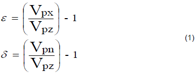
where Vpz = vertical velocity seen in well logs, Vpn = near offset velocity estimated from seismic data, and Vpx = horizontal component of velocity.
The delta anisotropic parameter, , is related to well-to-seismic mistie and requires well data to be quantified, whereas, the epsilon parameter, , requires long-offset approximately twice the target depth to be quantified. Offset VSP data are rarely acquired in many exploration projects and when they are available, they are often limited in areal coverage. In this study, an integrated approach using well and short offset seismic data, based on the degree to which checkshot and stacking interval velocity trends diverge with increasing depths was utilized to quantify and derive an optimum factor that successfully corrected seismically-derived velocity in AMFO field in the western Niger Delta transition zone, for improved quantitative seismic interpretation in the field. Ignoring velocity anisotropy in quantitative seismic interpretation and reservoir characterization workflows such as seismic amplitude variation versus offset (AVO) modeling and analysis, seismic inversion and pore pressure prediction, which require acoustic velocities would lead to inaccurate results with the overall effect of risking exploration for hydrocarbon.
LOCATION AND GEOLOGY
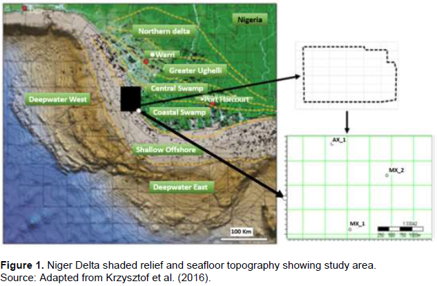
The “AMFO” field is situated in the south-western part of the Niger Delta coastal swamp depobelt (Figure 1). The field currently has three partly developed wells with most of the non-associated gas reservoirs only now being planned for development. The Niger Delta is Africa’s leading oil province (Reijers, 2011). It is subdivided into five distinctive depobelts most of which are bounded by a landward-trending normal listric growth fault and seaward-trending counter-regional fault system (Steele et al., 2009). The depobelts range from Eocene to Plio-Pleistocene in age.
The tertiary age Niger Delta siliclastic sediment deposits are classified into three lithostratigraphic units namely the Akata, Agbada and Benin Formations. The Benin Formation consists of massive deposits of mainly alluvial and upper coastal plain sands with a few shale interbeds. The Agbada Formation consists of alternating sequence of sandstones and shales, with sand-shale ratio decreasing with depth.
Most of the hydrocarbon reservoirs in the Niger Delta found in the sandstones of the Agbada Formation, where they are trapped in rollover anticlines fronting growth faults in channels and barrier sandstone bodies. The Akata Formation is the basal unit of the Tertiary Niger Delta complex, and is composed predominantly of medium to hard, dark grey shales with plant remains especially at its upper part. The structural pattern and stratigraphy of the Niger Delta are controlled by the interplay between rates of sediment supply and subsidence (Evamy et al., 1978; Doust and Omatsola, 1990).
MATERIALS AND METHODS
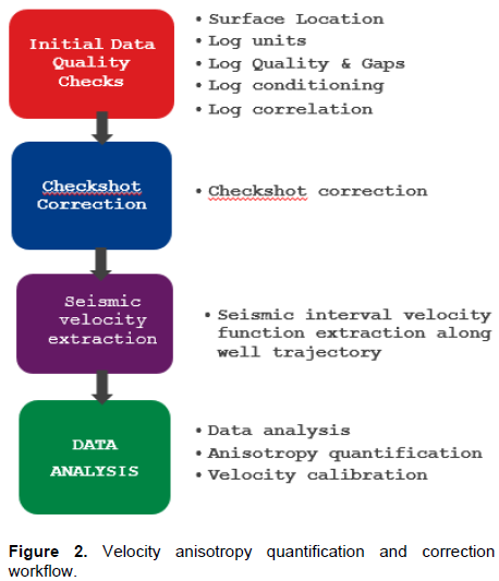
The dataset used for this study comprised seismic interval velocity field derived from 2008 processed vintage of the AMFO PSDM seismic data, and a suite of well logs from three wells (AX_1, MX_1 and MX_2) consisting of GR, RHOB, LL9D, CALI, NPHI and compressional sonic (DT), as well as checkshots and hole deviation data. The seismic data was acquired in 1998 using short offset (3,000 m cable length). The processing carried out in 1998 was aimed at addressing shallow channels and velocity variation, amidst attenuating steeply dipping long period multiples that were somewhat retained in the data after the initial processing. Major pre- and post-migration processing steps that were employed to address these challenges were true amplitude gain recovery, inverse-Q compensation, swell denoise and tau-P deconvolution, and post migration hi-resolution radon demultiple, respectively. This study focuses on quantification of velocity anisotropy derived from the post migrated seismic interval velocity field, and its correction. The workflow adopted for the study is as shown in Figure 2.
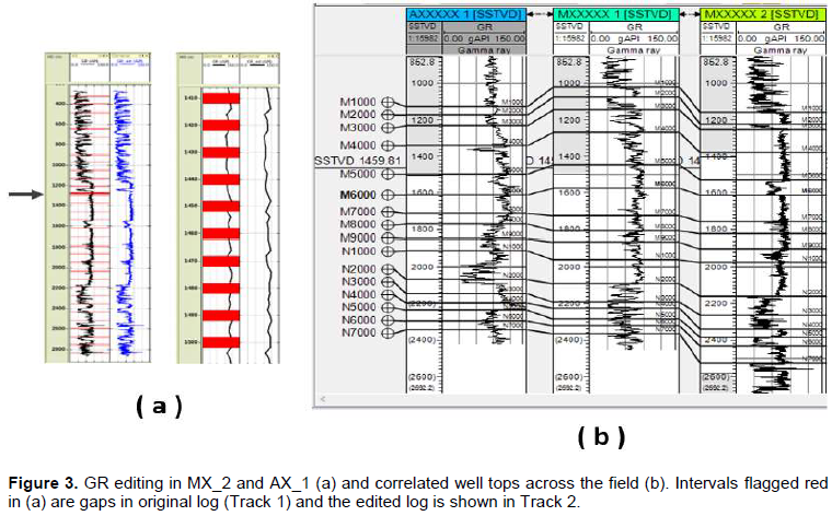
Starting point was to quality-check (QC) the relevant well logs (GR, CALI, DT and checkshots) and support data (well tops and deviations) for correct surface coordinates, units, general quality and gaps in the data. The GR log was key to providing lithology information and the caliper log, which was logged only in MX_1, provided a means of assessing the quality of the sonic log in that well. Overall, data quality is good, but GR in AX_1 and MX_2, as well as compressional sonic in MX_2 were heavily degraded with gaps which were filled to retain their quality. The edited GR logs were correlated across each well to pick well tops. This was necessary to provide qualitative information on velocity anisotropy across respective formations in the study area. Figure 3 shows the GR logs before and after their editing, and the correlated tops in the “AMFO” field.
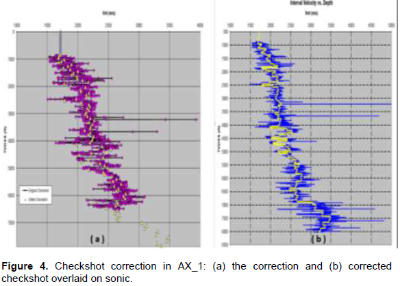
The checkshots provided the TZ information for extracting seismic interval velocity function along each well trajectory from the seismic interval velocity field. In order to extract accurate seismic velocity function along a well trajectory, the TZ information from the recorded checkshot data must be accurate and of high quality. This was ensured in this study by performing a detailed automated checkshot editing designed to automatically remove spurious records from the data based on calculated difference between original and internally interpolated checkshot interval velocities. Important input parameters for the calculation include the minimum and maximum interval velocity thresholds, the minimum allowed time difference between two neighboring input time units and the maximum interval velocity gradient. The input parameters for the checkshot correction in this study are 1850 m/s, 4500 m/s, 20 and 90, respectively. Figure 4 shows the checkshot editing in AX_1, overlaid on compressional sonic log.
Next, the edited checkshot and extracted seismic interval velocity function for each well were exported into Ikon Science’s RokDoc software for analysis. To ensure that the data were analyzed at similar depth locations, a measured depth (MD) to true vertical depth (TVD) conversion was first carried out following from which qualitative interpretation was done to detect the evidence, onset and degree of anisotropy in the data. Finally, the degree of delta anisotropy was quantified using Equation 1 , and correction functions derived to calibrate the seismic interval velocity along the well trajectories. The implementation is such that if  is delta anisotropy (in fraction) computed for a particular depth
  , then the calibrated seismic interval velocity at that depth is given by Equation 2:
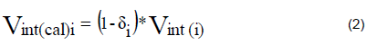
where Vint(cal)i = calibrated seismic interval velocity and Vint(i) = seismic interval velocity at depth i.
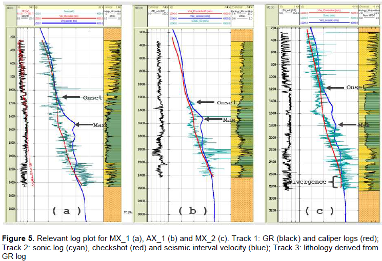
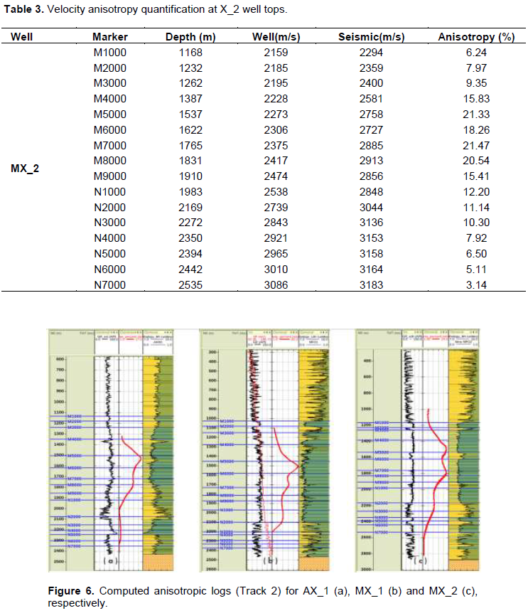
In order to avoid computation errors, the scaling was discontinued at the shallowest depth at which the interval velocity from checkshot and seismic interval velocity gave a good trend. This was particularly important in MX_2 (Figure 5c), for example, where the checkshot seemed to re-diverge after establishing a match with the seismic velocity at about 2,640 m TVDss.
RESULTS AND DISCUSSION
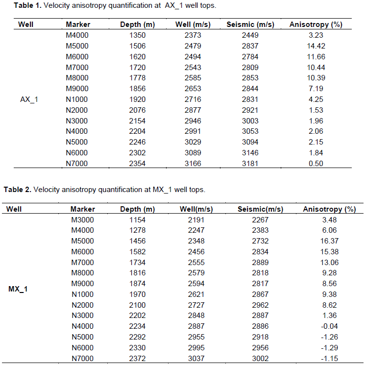
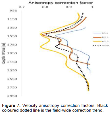
Figure 5 shows the relevant data used for the analysis, plotted in TVDss. Qualitatively, the onset of maximum anisotropy, indicated by the arrows, vary from about 1,100 m for the MX_1 well, to about 1,260 and 1,200 m for AX_1 and MX_2 wells, respectively. Maximum anisotropy is evident at about 1,530 m in MX_1 and AX_1, and 1,800 m in MX_2, respectively. Quantitative interpretation of the results shows that velocity anisotropy in the ´AMFO´ field ranges from about 1.36% of 1,100 m TVDss around Mx_1 to a maximum of 21.47% at around 1,537 m TVDss, with an average of about 12.3%. Tables 1 to 3 show the result of quantitative analysis of velocity anisotropy in each well at the various well tops. Onset of anisotropy is fairly uniform at about 1,100 m TVDss in the area. The high average anisotropy in the area can be attributed to the presence of thick shales as evident in the lithology log sets computed for the area. Figure 6 shows the anisotropy correction factor derived for each well and Figure 7 shows a single-trend correction factor for the entire field, which was derived in view of the good trend established by the correction factors for the individual wells. The advantage of the representative correction factor is that it could become possible to quickly create a reasonably accurate 3D velocity anisotropic field from this function using a “SynModel” tool by layer stripping or by using interpreted seismic horizons as control. The result could be utilized in pre-drill pore pressure prediction and other reservoir characterization workflows for improved exploration success.
CONCLUSION
By integrating well and seismic data, velocity anisotropy was quantified and seismic velocity corrected for anisotropy in a field situated in the Niger Delta coastal swamp depobelt. The seismic data was acquired using a short cable and as such, only the Thomsen’s delta anisotropy parameter was quantified in this study. The practical aspect of quantification and correction of velocity anisotropy is clearly shown in this work, and the method can be employed to quantify anisotropy on similar datasets acquired under any geologic setting. The method can be extended to produce accurate 3D velocity anisotropic model by constraining with interpreted seismic horizons for accurate rock property prediction away from the wellbore and improved reservoir characterization workflows with the overall effect of de-risking exploration for oil and gas.
CONFLICT OF INTERESTS
The authors have not declared any conflict of interests.
REFERENCES
|
Doust H, Omatsola ME (1990). Niger Delta, In: J. D. Edwards, P. A Santogrossi (eds.), Divergent/passive margin basins, American Association of Petroleum Geologists 1:239-248. |
|
|
Evamy BD, Haremboure J, Kamerling, P, Knapp WA, Molloy FA, Rowlands PH (1978). Hydrocarbon habitat of the Niger Delta; American Association of Petroleum Geologists Bulletin 62:1-39. |
|
|
Jones IF, Bridson ML, Bernitsas N (2003). Anisotropic ambiquities in TI media. First Break 21(4):29-35. |
|
|
Krzysztof M, Wojcik I, Espejo IS, Kaleijaye AM, Umahi OK (2016). Bright spots, dim spots: Geologic controls of direct hydrocarbon indicator type, magnitude, and detectability, Niger Delta Basin, Interpretation 4(3):45-69. |
|
|
Reijers TJA (2011). Stratigraphy and sedimentology of the Niger Delta, Geologos 17(3):133-162. |
|
|
Steele D, Ejedawe J, Adeogba T, Grant C, Filbrandt J, Ganz H (2009). Geological Framework of Nigeria Linked Shelf Extension and Deepwater Thrust Belts. AAPG Search and Discovery Article #90123©2011 AAPG Hedberg Conference, Tirrenia, Italy. |
|
|
Thomsen L (1986). Weak elastic anisotropy: Geophysics 51:1954-1966. |
|
|
Winterstein DF (1990). Velocity anisotropy terminology for geophysicists: Geophysics 55:1070-1088. |
|
Copyright © 2024 Author(s) retain the copyright of this article.
This article is published under the terms of the Creative Commons Attribution License 4.0


