Full Length Research Paper

ABSTRACT
The development of renewable energies is essential to meet the energy demand which is growing year after year. Africa has a strong solar potential which is, however, little exploited. The development of solar photovoltaic (PV) energy will be more favored with the democratization of performance monitoring and characterization tools for PV systems. Monitoring systems are very important because they allow the monitoring of the operation and control of PV installations in order to reduce maintenance costs and avoid undesirable power supply interruptions. There are several monitoring systems, more or less efficient, proposed on the market but they are often too expensive and not adapted to all existing systems. This paper presents a low-cost electronic board for monitoring and characterizing photovoltaic systems. The designed board is based on the ATMega328 microcontroller of the open-source development platform Arduino. It is composed of four blocks that allow the acquisition of electrical and environmental parameters. The board has been tested in monitoring mode with the follow-up of a small PV solar installation. The results of these experiments are consistent with what is found in the literature. Its use in characterization mode has allowed to obtain, in real time, the current-voltage and power-voltage characteristics. Compared to the results of the IV-500W tracer, the characterization results are consistent with an RMSE of 0.81 in voltage and 0.15 in current on all points measured. The design work is completed with the PCB design on Altium designer which resulted in the Gerber file.
Key words: Microcontroller, photovoltaic (PV) monitoring, PV characterization, PCB.
INTRODUCTION
The growing demand for energy coupled with the global challenge to reduce the use of fossil fuels, which pollute the environment, has greatly increased the interest in renewable energy sources (Corcelli et al., 2017). Africa has the highest solar potential in the world with 40% of the world's theoretical reserves (Liu, 2015). The exploitation of this potential requires equipment that allows the monitoring and characterization of systems in real conditions of use Traditional measurement methods (multimeters, oscilloscopes, thermocouples) require long processes and are not always accurate, as they require multiple human interventions in the process (Rahman et al., 2018). There are systems based on automated sensors available on the market to meet this need. However, in addition to being expensive, these systems have other limitations. Indeed, these systems are often energy consuming and require a high storage for defined data recording states. In addition, commercial tools have predefined functionalities, so users cannot make customized performance evaluations. Therefore, they do not meet the specific requirements of each installation (Hammoumi et al., 2018; Miri? and Nedeljkovi?, 2015; Rahman et al., 2018).
The use of open-source tools such as Arduino is becoming more and more common in the literature to develop monitoring systems for different types of systems (Rahman et al., 2018). For example, González and Calderón (2019) and Sugiartha et al. (2018)have developed prototypes of a monitoring and data acquisition system dedicated to autonomous systems and smart grids. Based on ATMega2560 of the Arduino Mega, the designed systems allowed to monitor the evolution of several parameters such as voltage, current, irradiance, temperature, etc. Other researchers have made a PV energy production monitoring and estimation system for a residential self-consumption system that uses an Internet of Things (IoT) platform (Rus-Casas et al., 2020). One of the many advantages of Arduino is that it is usable in harsh climatic conditions as evidenced by the work of (Touati et al., 2016)which proposed a measurement system to predict the performance of polycrystalline PV modules in a harsh environment (Doha) with wireless monitoring and data logging. This allowed them to find that the maximum power output of PV modules decreases by 30% for five months of dust exposure. The work of El Hammoumi et al. (2018)showed the advantages of Arduino-based data acquisition systems compared to traditional methods. However, the design work can be taken a step further by designing the layout for large-scale production.
In this paper, we propose a low-cost monitoring and data acquisition system based on the ATMega328 microcontroller of the Arduino UNO that allows monitoring and characterization of PV systems. The design work will be pushed with the design of the layout of the electronic board for a possible industrial production.
MATERIALS AND METHODS
Presentation of the proposed system
In order to measure the electrical and environmental parameters, a certain number of components made up of blocks are necessary. The board is thus composed of four blocks (voltage, current, environmental parameters and control) that communicate with the Arduino UNO board, in particular the ATMega328 microcontroller to monitor and characterize PV systems.
The voltage acquisition block
The analog inputs of the Arduino UNO cannot take voltage values greater than 5V. So, to measure larger voltages, we will use the voltage divider. This is one of Kirchhoff's laws which makes it possible to know the voltage at the terminals of a set of resistors in series knowing that of one of the resistors in series. Figure 1 illustrates the principle of the voltage divider.
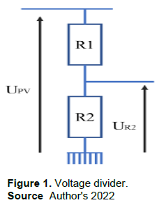
In addition to the bridge divider, the block includes smoothing capacitors (filters), a blue LED that lights up as soon as the system detects a voltage higher than 1 V and an alarm composed of a red LED and a beeper that are activated as soon as the system starts to detect a voltage close to the maximum allowable voltage for the system (55 V for this resistor ratio).
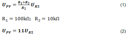
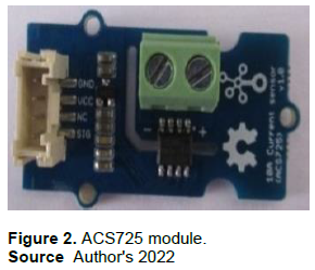
The current acquisition block
Intended to measure the current, this block consists of the ACS725 module. It is an integrated circuit that allows the reading of unidirectional direct current through a Hall effect sensor. The main characteristics (ACS725 Datasheet)of the ACS725 module (Figure 2) are presented in Table 1.
Measurement of environmental parameters
The environmental parameters measurement block allows to:
(1) Measure the ambient temperature,
(2) Measure the relative humidity,
(3) Provide an indication of the incident light.
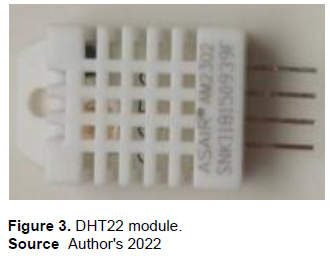
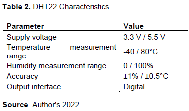
The DHT22 module (Figure 3) has been chosen for temperature and relative humidity measurements. A capacitive sensor element measures the relative humidity and the temperature is measured by a negative temperature coefficient (NTC) thermistor. The DHT22 sensor (DHT22 Datasheet) has excellent reliability and long-term stability. Its main features are show in the following in Table 2.
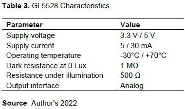
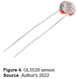
The GL5528 photoresistor (or LDR: light dependent resistor) is used to have an idea on the quantity of incident light. It is a light sensor designed with semiconductors whose resistivity varies according to the light exposure. This variation of the resistance with the luminosity is not linear, but rather logarithmic. However, this property of LDRs will not have any impact in our case, since the sensor will only serve to warn the user of the board that the light density is sufficient or not to proceed with the characterization of a GPV. When the irradiance is higher or equal to 700 W/m², we can proceed to the characterization according to the IEC 60904-3 and IEC 60891 standards [13,14]. Thus, the green LED lights up to indicate this to the user of the board. Otherwise, this LED is off. Table 3 summarizes some technical information (GL5528 Datasheet)of the LDR GL5528 shown in Figure 4.
The control block
The control block is mainly composed of a yellow LED, a push button and some resistors. When the board boots up and initializes, the yellow LED will flash three times to let the user know it is ready to go. Two situations arise:
(1) Either the user presses the push-button for one second to tell the microcontroller to operate in characterisation mode (measurements are taken every 30 ms)
(2) Or the user does not press the push-button and the board operates in monitoring mode (measurements are made every minute).
The user has the option to use the characterisation mode after each measurement (as soon as the yellow LED flashes again every minute).
The intelligent block
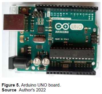
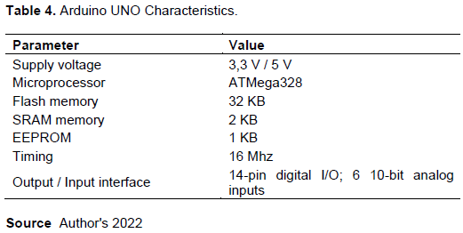
The intelligent block is constituted by the Arduino UNO (Figure 5) electronic prototyping board, particularly its ATMega328 microcontroller. The Arduino UNO board meets our needs in terms of memory space, number of inputs/outputs and is not bulky. In Table 4, are some technical specifications (ATMEGA328 Datasheet)of the UNO.
Software tools
The four software used in this work are: the Arduino integrated development environment (IDE), Proteus including ISIS, the PLX-DAQ program, and Altium Designer.
Arduino IDE
The Arduino IDE is a cross-platform tool that offers everything you need to edit a program, check its syntax, then upload the code to an Arduino board, that is, program the board’s microcontroller (Evans, 2011).
Proteus (ISIS)
Proteus is a Computer Aided Design (CAD). It is composed of a set of software that allows the design of a complete electronic system; from the basic diagram to the output of the layout through the simulation. The ISIS program is used in this work for the simulation of the board before the experiment (Asparuhova et al., 2018; Su and Wang, 2010).
PLX-DAQ
This is a microcontroller data acquisition tool developed by Parallax for Microsoft Excel. Any of our microcontrollers connected to any sensor and to the serial port of a PC can send data directly into the Excel spreadsheet via PLX-DAQ (Sreenivas Rao and Shivakumar, 2020).
Altium designer
Altium designer is a professional PCB and electronic design automation tool. With Altium designer, it is possible to design a Printed Circuit Board (PCB) from a schematic editor to the output of the Gerber file. This is the tool that was used for the design of the PCB on the computer (“Altium Designer – logiciel de conception de circuits imprimés,” n.d.; Caron, n.d.).
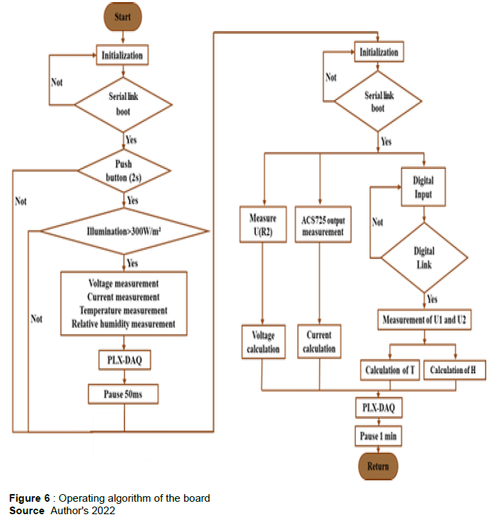
Operating algorithm
The board operates in two modes: monitoring and characterization. These two modes are governed by an operating algorithm (Figure 6) which defines the succession of the different steps. If the two modes have in common the initialization or the measurements of the electrical and environmental parameters, the characterization mode has certain particularities. In fact, for the card to work in characterization mode, the user must press and hold the board after the yellow LED flashes; then the microcontroller checks that the irradiation is greater than 700 W/m². If this is not the case, it leaves the characterization mode to operate in monitoring mode.
RESULTS AND DISCUSSION
Simulation
After having chosen the components to be used for the realization of the card, this one was simulated using ISIS following the algorithm presented in Figure 6. The simulation scheme is presented in Figure 7.
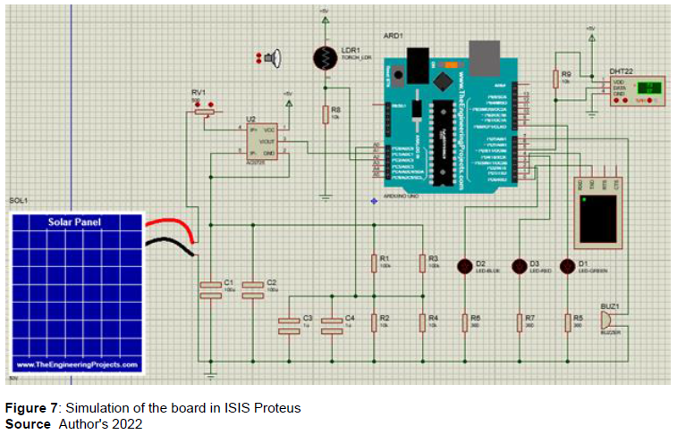
The simulation of the diagram in Figure 7 gave satisfactory results in that we were able to recover the voltage, current and power values. This true for the environmental parameters of temperature and relative humidity. The light sensor also played its role well via the green LED, because every time the solar simulator provided enough light, the blue LED lit up. The alarm also worked well with the red LED and the beeper turned on every time the solar panel voltage is greater than or equal to 50 V. So, we can say that the card is validated by simulation.
Presentation of prototype and lay-out
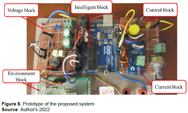
Here is dedicated to the realization of the first prototype. 100 Ω rheostat is also added to the control block PCB to act as a resistive load when characterizing small modules with a short circuit current of less than 100 mA. These different blocks communicate with the Arduino UNO board which is the smart block. The different blocks are joined together with the help of a Plexiglas support to form the first prototype presented in Figure 8.
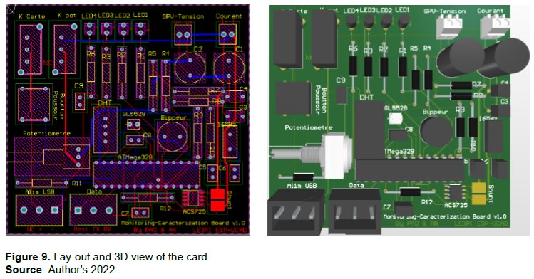
With the prototype functional, the design work continued with the design of the PCB on the computer. The Altium designer placement/routing tool was used to perform this task. It is important to note that only the ATMega328 microcontroller, a quartz clocking at 16 MHz and two smoothing capacitors are elements of the Arduino UNO board that are essential for the proper functioning of the proposed system. The communication between the computer (USB protocol) and the microcontroller (UART protocol) will be ensured by a cable equipped with a FTDI chip. The layout and a 3D view of the map are presented in Figure 9.
Monitoring mode test
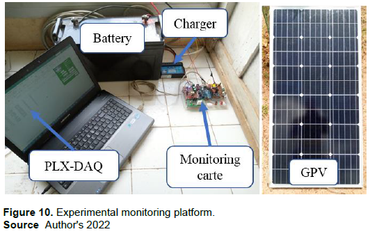
The use of the card in monitoring mode was done according to the assembly (Figure 10) composed of a PV solar panel with a power of 80 watts (XHGD-80W), a 12 V-100 Ah battery (Jarett), a 12/24 V PWM charge controller, the prototype card and a laptop. The objective of this manipulation was to follow the current and the voltage (thus also the power) of load which the photovoltaic generator provides to charge the battery during a whole day. The environmental parameters such as temperature and relative humidity were also recorded.
This setup is used to do the monitoring several times. As an illustration, the results of the experiments done on August 20, 2021 are presented in Figure 11.
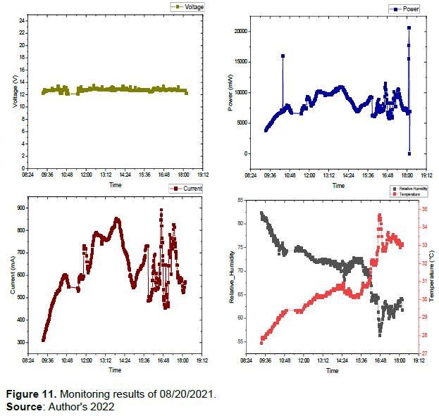
Figure 11 represents the data measured by the prototype's sensor network during the monitoring experiments on August 20, 2021. It can be seen that the charging voltage is around 12 V (between 12.2 and 13.2 V) all day long. This is explained by the fact that the charge controller used is of the PWM type and that the voltage of the GPV is therefore at the same time the voltage at the terminals of the battery whose charge it regulates (Sharif et al., 2009). As for the current, it varied a lot in a rather irregular way during the day; this is consistent with the literature and previous known experiments. Indeed, these variations are due to the fact that the sunlight was sometimes obstructed by cloudy passages (Fuentes et al., 2014). This phenomenon was frequent since the measurements were made in winter and there were frequent cloudy periods around 3 pm. These cloudy passages are accompanied by a drop in temperature at this time of day.
The power being the product of the voltage (almost constant) and the current; its evolution is rather similar to that of the current. The temperature and relative humidity had normal evolutions, according to the literature, with an increase of the temperature and a decrease of the relative humidity from the morning. These two environmental parameters often have inverse evolutions; when one increases, the other decreases (Fall et al., 2006; Sugiartha et al., 2018).
Characterization mode test
Figure 12 shows the experimental configuration of the prototype in characterization operation. The setup is composed of a variable resistor, a GPV (Q.CELL QC-C05), the electronic board designed for this work and a laptop. In addition, the tracer IV-500W from HT instruments is used as a basis for comparison of the results obtained with the proposed system. As an illustration, a part of the obtained results is presented in Figure 13.
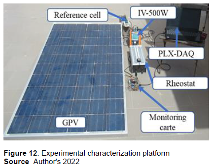
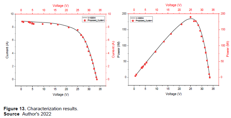
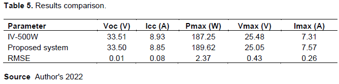
Figure 13 shows a comparison of the characterization results from the experiment. As shown by the I-V and P-V characteristic curves, the results of the proposed system are more or less in line with those of the IV-500W tracer with an RMSE (Root Mean Square Error) of 0.81 in voltage and 0.15 in current on all points. We can identify the main characteristic points of a PV module which are presented in Table 5 with their RMSE. We note that the measurements of the open circuit voltage (Voc) and the short circuit current (Icc) are the most accurate with RMSE very close to 0 while the measurement of the maximum power (Pmax) is the least accurate with a RMSE of 2.37. Referring to the works of El Hammoumi et al. (2018) and Hammoumi et al. (2018), these differences are acceptable in view of the concessions made in the price of the equipment. However, there are some irregularities on the points measured by the proposed system. This could be improved by using a more accurate shunt and by adding a second measurement channel for each electrical parameter to make averages.
Collecting a larger number of points would also improve the quality of the measurement.
Compared to the manufacturer's data, the experimental results show a shortfall of 40.38W since the tested module has a Pmax of 230W in Standard Test Condition STC). This coincides with some previous observations and can be explained by the fact that the characterization was done under real conditions of use different from the standard conditions (Issa et al., 2017). Indeed, the measurements were made in an environment where the irradiance was relatively low (749.1 W/m²) while the temperature of 31°C was high. These climatic conditions negatively impacted the performance of the PV module (Dubey et al., 2013).
CONCLUSION
The objective of this work was to develop an open-source and low-cost instrumentation tool for monitoring and characterizing PV systems. The prototype has a manufacturing cost estimated at 36,82$ US (price of components and PCB). The work with respect to the different stages of the design that are the dimensioning of components, simulation and experimentation in laboratory, this allowed the design of the layout which resulted in the Gerber file that is exploitable by any competent laboratory for an industrial production of the proposed system.
The experiments carried out with the prototype in monitoring allowed to follow the electrical and environmental parameters of a small installation. The results obtained are in line with previous known experiments. In characterization mode, the test results were compared with those obtained using the IV-500W tracer. It was found that the results of the proposed system are consistent with those of the tracer IV-500W with an RMSE of 0.81 in voltage and 0.15 in current on all points measured, which allowed the validation of the prototype.
Even if the system proposed in this paper works with a fairly good accuracy, it must be improved in order to better meet the needs of everyone. To do this, increasing the measurement limits (currently 550W) would allow the system to be usable in relatively large installations. One method of making the measurements more accurate would be to increase the number of measurement points during testing. To allow the board to be portable and autonomous, the addition of a display would be very beneficial to the users of the proposed system. Moreover, with the development of IoT in recent years, it would be very interesting to add a wireless connectivity module to allow remote monitoring in installations.
CONFLICT OF INTERESTS
The authors have not declared any conflict of interests.
REFERENCES
|
ACS725 Datasheet - Allegro MicroSystems, LLC | DigiKey, (n.d). URL |
|
|
Altium Designer - logiciel de conception de circuits imprimés, n.d. URL |
|
|
Asparuhova K, Shehova D, Lyubomirov S (2018). Using Proteus to Support Engineering Student Learning: Microcontroller-Driven Sensors Case Study. 2018 IEEE XXVII International Scientific Conference Electronics - ET. pp. 1-4. |
|
|
ATMEGA328 Datasheet - Atmel, (n.d). URL |
|
|
Caron S (n.d). Altium Designer WorkFlow - D'une étincelle d'idée jusqu'aux gerbers 25. |
|
|
Corcelli F, Ripa M, Ulgiati S (2017). End-of-life treatment of crystalline silicon photovoltaic panels. An emergy-based case study. Journal of Cleaner Production. 161:1129-1142. |
|
|
DHT22 Datasheet - Aosong Electronics - Temperature and Humidity Sensor (n.d). URL |
|
|
Dubey S, Sarvaiya JN, Seshadri B (2013). Temperature dependent photovoltaic (PV) efficiency and its effect on PV production in the world-a review. Energy Procedia 33:311-321. |
|
|
El Hammoumi A, Motahhir S, Chalh A, El Ghzizal A, Derouich A (2018). Low-cost virtual instrumentation of PV panel characteristics using Excel and Arduino in comparison with traditional instrumentation. Renew. Wind, Water, and Solar 5:3. |
|
|
Evans B (2011). Beginning Arduino Programming. Springer. |
|
|
Fall S, Niyogi D, Semazzi FHM (2006). Analysis of Mean Climate Conditions in Senegal (1971-1998). Earth Interactions 10(5):1-40. |
|
|
Fuentes M, Vivar M, Burgos JM, Aguilera J, Vacas JA (2014). Design of an accurate, low-cost autonomous data logger for PV system monitoring using ArduinoTM that complies with IEC standards. Solar |
|
|
Energy Materials & Solar Cells 130:529-543. |
|
|
GL5528 Datasheet - Nanyang Senba Optical Electronic, (n.d). URL |
|
|
González, I, Calderón AJ (2019). Integration of open source hardware Arduino platform in automation systems applied to Smart Grids/Micro-Grids. Sustain. Energy Technology Assess 36:100557. |
|
|
Hammoumi AE, Motahhir S, Chalh A, Ghzizal AE, Derouich A (2018). Real-time virtual instrumentation of Arduino and LabVIEW based PV panel characteristics. IOP Conference Series: Earth and Environmental Science 161:012019. |
|
|
Issa F, Ababacar N, Diouma K, Moustapha T, Cheickh S, Lat-Grand N (2017). Evaluation of the impact of partial shading and its transmittance on the performance of crystalline silicon photovoltaic modules. International Journal of Physical Sciences 12(21):286-294. |
|
|
Liu Z (2015). Global energy interconnection, illustrée. ed. Academic Press. |
|
|
Miri? S, Nedeljkovi? M (2015). The solar photovoltaic panel simulator. Revue Roumaine Des Sciences Techniques 60:273-281. |
|
|
Rahman MM, Selvaraj J, Rahim NA, Hasanuzzaman M (2018). Global modern monitoring systems for PV based power generation: A review. Renewable and Sustainable Energy Reviews 82:4142-4158. |
|
|
Rus-Casas C, Jiménez-Castillo G, Aguilar-Peña JD, Fernández-Carrasco JI, Muñoz-Rodríguez FJ (2020). Development of a Prototype for Monitoring Photovoltaic Self-Consumption Systems. Electronics 9:67. |
|
|
Sharif GM, Islam SMM, Salim KM (2009). Design & construction of microcontroller based maximum power point PWM charge controller for photovoltaic application. 2009 1st International Conference on the Developments in Renewable Energy Technology pp. 1-4. |
|
|
Sreenivas Rao MV, Shivakumar M (2020). PLX-DAQ-Based Wireless Battery Monitoring System for Obstacle Avoidance Robot. Shreesha, C., Gudi, R.D. (Eds.), Control Instrumentation Systems, Lecture Notes in Electrical Engineering. Springer, Singapore pp. 133-140. |
|
|
Su B, Wang L (2010). Application of Proteus virtual system modelling (VSM) in teaching of microcontroller. 2010 International Conference on E-Health Networking Digital Ecosystems and Technologies pp. 375-378. |
|
|
Sugiartha N, Sugina IM, Putra IDGAT, Indraswara MA, Suryani LID (2018). Development of an Arduino-based Data Acquisition Device for Monitoring Solar PV System Parameters. Proceedings of the International Conference on Science and Technology (ICST 2018). Atlantis Press, Bali, Indonesia pp. 995-999. |
|
|
Touati F, Al-Hitmi MA, Chowdhury NA, Hamad JA, San Pedro Gonzales AJR (2016). Investigation of solar PV performance under Doha weather using a customized measurement and monitoring system. Renewable Energy 89:564-577. |
|
Copyright © 2024 Author(s) retain the copyright of this article.
This article is published under the terms of the Creative Commons Attribution License 4.0


