Full Length Research Paper

ABSTRACT
Strengthening fibers and layers in nanocomposites can make these materials suitable for many applications such as automobile, sport goods, aerospace, etc. Currently, scientists are still looking for materials with higher strength, but still lightweight because of consuming less fuel and energy in industries such as automobile and aerospace. In this research, by considering thermal fatigue resistance management technology between the nanofibers and layers, it was attempted to achieve a new super reinforced MWCNT/epoxy. This nanocomposite consists of MWCNTs with 25 nm diameter, triple-walled CNTs and single layer graphene. The reinforcing theory, which is suggested in this study, is to cover the triple-walled CNT with MWCNT with 25 nm diameter. Furthermore, all of the empty space between interior of triple-walled CNT and MWCNT should be filled out with rolled graphene layers. The recommended super reinforced MWCNT/epoxy offers a very high strength, but still is lightweight. Furthermore, the recommended nanocomposite has a high thermal fatigue resistance.
Key words: Super reinforced nanocomposite, thermal fatigue resistance, coefficient of thermal expansion, Nano-fibers, single layer grapheme, MWCNT.
INTRODUCTION
It has been decades that many industries such as automobile, sport goods, aerospace, etc., are been applying composite materials in their productions (Fitzer et al., 1984; Tamilarasana et al., 2015; Petersson et al., 2013; Park et al., 2012). The reason is that the mechanical properties of composites have both flexibility due to the mechanical properties of matrix and high strength due to the fiber mechanical properties. The combination of fibers high strength and matrix flexibility creates appropriate mechanical properties for the composite materials.
Currently, with the advancements in materials science and engineering, many industries are using nanocomposites because of their enhanced mechanical properties such as higher strength and further lightweight (Camargo et al., 2009; Tyagi and Tyagi, 2014; Okpala, 2013; Hussain et al., 2006). The great example of a high-strength nanocomposite is carbon nanotube/epoxy nanocomposite that has a higher strength in comparison with carbon fiber/epoxy composite.
In 2014 (Anvari, 2014), it was proven that the degradation of Inter-Laminar Shear Strength (ILSS) in Unidirectional Carbon Fiber/Epoxy Composite (UCFEC) is the most important issue in de-bonding and failure of UCFEC exposed to thermal fatigue cycles. With further research in this area (Anvari, 2017), it was found that degradation of ILSS in UCFEC appears to be due to the mismatch of Coefficients of Thermal Expansion (CTE) between carbon fibers and epoxy. This significant conclusion can contribute to have the best design in composites and nanocomposites that can tolerate high thermal cycles. For having the best design, it seems enough to try to have a best match for CTEs between the nanocomposites’ components such as fibers and epoxy. It means that according to this theory, fibers and epoxy should have similar values of CTEs to offer less Inter-Laminar Shear Stress (ILSs) and higher thermal fatigue life. This procedure can be named as “Thermal Fatigue Resistance Management Technology” (TFRMT).
Many studies have been performed until now to investigate the thermal fatigue resistance of nanocomposites (Mallick and Zhou, 2003; Genedy et al., 2015). Nevertheless, it appears that there is no research related to TFRMT for unidirectional nanocomposites.
This research, by applying TFRMT theory, has tried to offer the best Super Reinforced MWCNT/Epoxy Nano-composite (SRMWCNTE) that contains very high strength, but still lightweight and with high thermal fatigue resistance. This new SRMWCNTE can be applied in many applications such as aerospace and automobile industries. SRMWCNTE can be very advantageous especially in space industry that very high strength, thermal fatigue resistance, and lightweight structures are required.
EXPERIMENTAL PROCEDURES
“Spinnable MWCNT arrays were obtained by chemical vapor deposition using C2H2 and FeCl2 as the base material and the catalyst, respectively. The diameter of the MWCNTs was measured using a transmission electron microscope (TEM, JEOL JEM-2100F, Japan). A partially cured epoxy resin (B-stage epoxy) with a release paper was used as the starting material, where the epoxy resin comprised bisphenol-A type epoxy, novolac-type epoxy, and an aromatic diamine curing agent. The epoxy resin was then impregnated into the MWCNT monolithic sheet at 90°C for 3 min between the steel plates of a hot press (AS ONE AH-4015, Japan). After peeling off the release paper from the MWCNT sheet now impregnated with the epoxy resin (prepreg sheet), the prepreg sheet was cured at 130°C for 1.5 h at a pressure of 1 MPa using the hot press, forming a film specimen” (Shirasu et al., 2017).
“The TWCNT monolithic sheets were drawn out of the TWCNT arrays and wound onto a rotating plate. Raman scattering spectroscopy (JASCO, NRS-5100, Japan) was used to analyze the vibrational modes of TWCNTs. The measurements were carried out at room temperature under ambient conditions using an argon ion laser with an excitation wavelength of 532 nm. Aligned TWCNT/epoxy composites were prepared by a hotmelt prepreg method, wherein the MWCNT monolithic sheet was preimpregnated with an epoxy matrix” (Shirasu et al., 2017).
“A stacked TWCNT monolithic sheet about 20 mm wide and about 45 mm in length was placed on a polytetrafluoroethylene sheet and covered with the epoxy resin film with the release paper.
The weight fraction of TWCNTs was calculated from the masses of the TWCNT sheets (before impregnation of the epoxy) and the composites. Having obtained the weight fraction of the composites, TWCNT volume fractions were determined assuming that the densities of the epoxy and TWCNTs were 1.2 and 2.0 g/cm3. The TWCNT volume fraction was adjusted by changing the number of layers of TWCNT monolithic sheets and the values for the samples prepared were found to be in the range of 9 to 31 vol.%. Because the areal density of the TWCNT monolithic sheet per layer varies according to the TWCNT diameter and each batch of MWCNT arrays (1 to 2 TWCNT arrays have been used to prepare each TWCNT monolithic sheets), it is difficult to control in advance the TWCNT volume fraction of the composites for each type of TWCNTs. Microstructural observations using a scanning electron microscope (SEM, JEOL JSM6510, Japan) and TEM indicated that the epoxy resin well penetrated between TWCNTs and that densely aligned TWCNT composites were successfully fabricated using this processing method with only a limited amount of pores” (Shirasu et al., 2017).
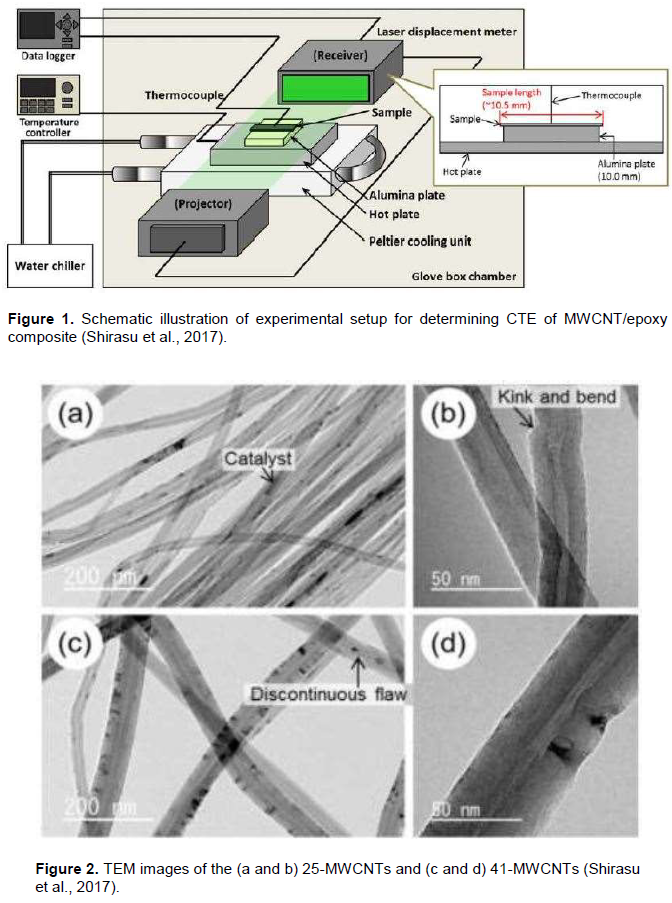
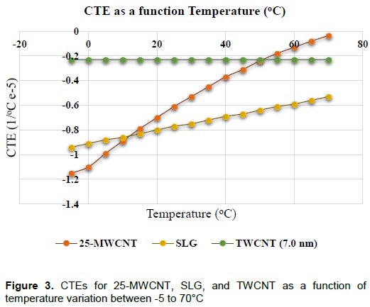
“The CTE of the aligned TWCNT/epoxy composite films was measured using the experimental setup. The dimensions of the composite film sample were 10.5 mm × 2 mm × 0.019 - 0.030 mm (length × width × thickness), where the length is measured along the direction parallel to the MWCNT alignment. The composite film sample and an alumina plate of width 10.0 mm (used as a specimen holder) were placed on a hot plate. The assembly was further set on a Peltier cooling stage. The temperature was controlled by using the hot plate and Peltier cooling apparatus, and the sample temperature was measured by a thermocouple placed in contact with the composite film sample. The length change was then measured by a laser displacement meter (Keyence LS-7600, Japan) over the temperature range 10 to 90°C and with a heating rate of 10°C/min” (Shirasu et al., 2017). Figure 1 (Shirasu et al., 2017) shows the schematic illustration of experimental setup for determining CTE of TWCNT/epoxy composite. Furthermore, Figure 2 (Shirasu et al. 2017) illustrates the TEM images of the (a and b) 25-MWCNTs and (c and d) 41-MWCNTs.
PROBLEM FORMULATION
In the methods part of the work, the procedure for super reinforcing the MWCNT/epoxy is described precisely in theoretical level. As it is mentioned previously, super reinforcing of MWCNT/epoxy was performed by the application of TFRMT.
TFRMT procedure can be performed according to the minimum mismatch of CTEs (Δαmin) between the attached layers and/or fibers based on Equation (1). The minimum mismatch of CTEs between the layers will result in less ILSs.
ILSs= Δα.ΔT.G (1)
In Equation (1) (Anvari, 2018), Δα is the mismatch of CTEs between the neighbor layers or fibers, or difference of CTEs between two components (both could be either fibers or layers attached).
The goal in this study is to arrange the Triple-Walled CNT (TWCNT), MWCNT, and Single Layer Graphene (SLG) in such an order that result in minimum mismatch between CTEs and can strengthen the nanocomposite.
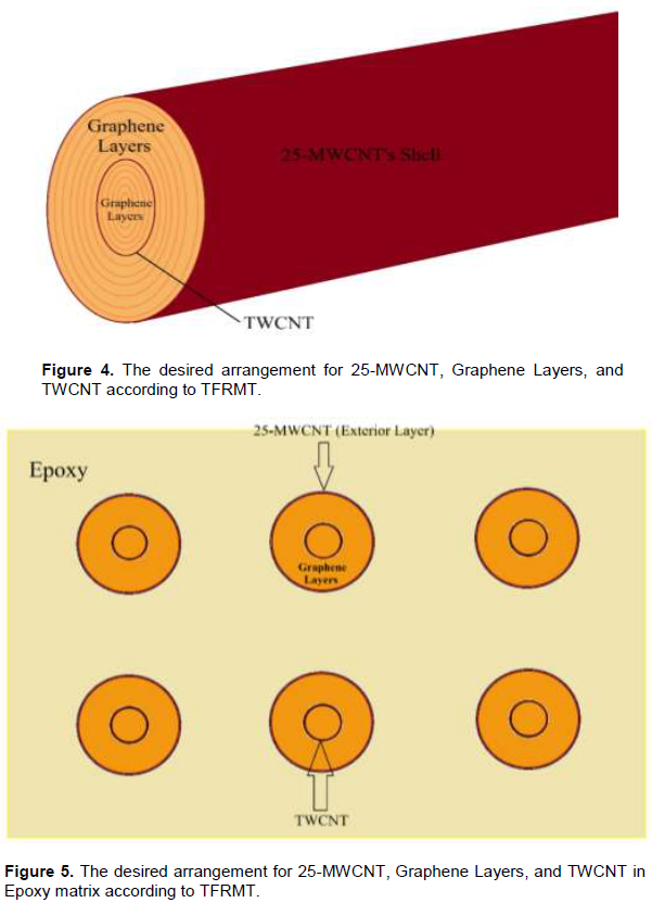
In Figure 3 (Shirasu et al., 2017), CTEs of 25-MWCNT (25 nm diameter MWCNT), SLG, and TWCNT (7.0 nm diameter) as a function of temperature variation between -5 and 70°C is illustrated.
The main objective here was to arrange these nanomaterials in a way to derive the minimum mismatch of CTEs. As it has been proven in the study carried out by Anvari (2017), the minimum mismatch of CTEs will result in less ILSs that could enhance the thermal fatigue life of MWCNT/epoxy. The main reason for choosing 25-MWCNT, SLG, and TWCNT for reinforcing the Nanocomposite is that according to Figure 3, these nanomaterials have very close values for CTEs. Thus, based on equation (1) the ILSs between these nanomaterials will decrease and thermal fatigue life will increase, which are the significant goals in this research.
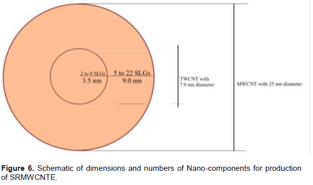
In Figures 4 and 5, the desired arrangement of 25-MWCNT, SLG, and TWCNT, within MWCNT/epoxy is shown. Based on Equation (1), and the experimental results obtained in 2017 (Shirasu et al., 2017), this arrangement will result in minimum mismatch between the CTEs of 25-MWCNT, SLG, and TWCNT
RESULTS AND DISCUSSION
According to Figure 3, CTEs for 25-MWCNT, SLG, and TWCNT are close numerical values. Thus, in the state that they are exposed to thermal cycles, less ILSs would be induced between them.
The arrangement of these nanomaterials for strengthening mechanism is based on their dimensions. The diameter of 25-MWCNT was 25 nm and the diameter of TWCNT was 7.0 nm (Shirasu et al., 2017). Therefore, TWCNT has smaller diameter in comparison of that for 25-MWCNT. Consequently, TWCNT could place at interior empty space of 25-MWCNT. The radius of 25-MWCNT was 12.5 nm and the radius of TWCNT was 3.5 nm. It means by placing TWCNT in the middle interior empty space of 25-MWCNT, there was about 9.0 nm empty space between 25-MWCNT and TWCNT.
According to the latest data related to the thickness of SLG, it appears that its thickness varies between 0.4 to 1.7 nm (Shearer et al., 2016). It means that in the empty space between 25-MWCNT and TWCNT, which is about 9.0 nm, 5 to 22 graphene layers can be placed. Or 5 to 22 SLGs can be rolled around TWCNT to fill out this space. On the other hand, the radius of TWCNT was about 3.5 nm. Hence, 2 to 8 rolled SLGs can be placed at interior space of TWCNT. This design theory is illustrated in Figure 6.
For performing a thermal analysis for SRMWCNT, it is easy to use the values of CTEs for 25-MWCNT, SLG, and TWCNT because they are all negative and close to each other in temperature range -5 to 70°C, according to Figure 3. It means that while SRMWCNT is cooling relative to ambient temperature (23°C), 25-MWCNT, SLG, and TWCNT were expanding in axial direction. On the other hand, when SRMWCNT is heating, all of them were contracting in axial direction. Due to the close CTEs numerical values between these nanofibers and Nano-layers, there is a very small probability to break bonds between them in the state that they are exposed to thermal cycles. Thus, thermal fatigue life of SRMWCNT increases with using thermal management technology. Furthermore, with filling out the interior part of 25-MWCNT with high strength TWCNT and SLG, the strength of SRMWCNTE increase significantly.
The mechanism which enhances the thermal fatigue life of SRMWCNT, is the reduction of ILSs between the nanolayers and/or nanofibers. The reason is that increasing ILSs between the layers and/or fibers, also increases stress concentration at interface areas between them. Stress concentration between the nanolayers and/or nanofibers can induce crack initiation and/or propagation. Furthermore, with the continue thermal cycles imposed on nanocomposite, crack propagation can cause fracture in the specimen. The aim of this research was to decrease the ILSs between the layers and/or fibers by applying TFRMT theory to decrease the stress concentration, crack initiation and/or propagation, and finally prevent or postpone the nanocomposite thermal fatigue failure which can occur with fracture.
CONCLUSIONS
In this study, by using TFRMT theory with applying Equation (1), a novel model for strengthening MWCNTE is suggested. The new nano-composite material is named SRMWCNTE, which is suitable for thermal cycles environments because of its thermal fatigue resistance characteristic. Thus, SRMWCNTE can be applied in many applications such as automobile and aerospace industries because of very high strength, lightweight, and thermal fatigue resistance property. Additionally, the new model can be highly advantageous in space industry because space structures are exposed to extreme hot and cold temperatures, and thermal cycles. Moreover, space structures need to be highly strong because of possible impact with space debris and meteorites. Hence, it appears that the application of SRMWCNT in structures is an appropriate choice for aerospace industry.
It is recommended to produce SRMWCNTE and perform experimental procedures to simulate extreme thermal cycles within, equal, and beyond -183 to 120°C to measure the effect of these thermal cycles on mechanical and thermal properties of this super reinforced nanocomposite material. The recommended temperature range for thermal cycles are coldest temperature on Titan, Saturn’s moon (-183°C) (Lorenz and Mitton, 2002) and maximum ambient temperature in Low Earth Orbit (Park et al., 2012). The results of the recommended experiments can contribute to predict thermal fatigue life or thermal cycles to failure for SRMWCNTE in future possible up-coming missions to space especially Titan (Regius, 2016) because recently, Titan is identified as one of the candidates for second home of human in solar system (Regius, 2016).
CONFLICT OF INTERESTS
The authors have not declared any conflict of interests.
REFERENCES
|
Anvari A (2014). Fatigue life prediction of unidirectional carbon fiber/epoxy composite in Earth orbit. International Journal of Applied Mathematics and Mechanics 10(5):58-85. |
|
|
Anvari A (2017). Fatigue Life Prediction of Unidirectional Carbon Fiber/Epoxy Composite on Mars. Journal of Chemical Engineering and Materials Science. 8(8):74-100 |
|
|
Anvari A (2018). Thermal Life of Carbon Structures: From the Earth to after the Titan. International Journal of Aerospace Engineering Vol. 2018 Article ID 7628614:6 pages |
|
|
Camargo PHC, Satyanarayana KG, Wypych F (2009). Nanocomposites: Synthesis, Structure, Properties and New Application Opportunities. Materials Research 12(1):1-39 |
|
|
Fitzer E, Gkogkidis A, Heine M (1984). Carbon fibres and their composites (A Review). High Temperatures-High Pressures 16:363-392 |
|
|
Genedy M, Daghash S, Soliman E, Taha MMR (2015). Improving Fatigue Performance of GFRP Composite Using Carbon Nanotubes. Fibers 3: 13-29; |
|
|
Hussain F, Hojjati M, Okamoto M, Gorga RE (2006). Review article: Polymer-matrix Nanocomposites, Processing, Manufacturing, and Application: An Overview. Journal of COMPOSITE MATERIALS 40(17):1511-1575 |
|
|
Lorenz R and Mitton J (2002). Lifting Titan's Veil; Exploring the giant moon of Saturn. Cambridge University Press. |
|
|
Mallick PK, Zhou Y (2003). Yield and fatigue behavior of polypropylene and polyamide-6 nanocomposites. JOURNAL OF MATERIALS SCIENCE 3(8):3183-3190 |
|
|
Okpala CC (2013). Nanocomposites – An Overview. International Journal of Engineering Research and Development 8(11):17-23 |
|
|
Park SY, Choi HS, Choi, WJ, Kwon H (2012). Effect of vacuum thermal cyclic exposures on unidirectional carbon fiber/epoxy composites for low earth orbit space applications. Composites: Part B. 43:726-738. |
|
|
Petersson H, Motte D, Bjarnemo R (2013). Carbon Fiber Composite Materials in Modern Day Automotive Production Lines – A Case Study. Proceedings of the ASME 2013 International Mechanical Engineering Congress & Exposition IMECE2013 November 15-21, San Diego, California, USA |
|
|
Regius C (2016). Titan: Pluto's Big Brother, The Cassini-Huygens spacecraft and the darkest moon of Saturn. 1th edition. |
|
|
Shearer CJ, Slattery AD, Stapleton AJ, Shapter JG and Gibson CT (2016). Accurate thickness measurement of graphene. Nanotechnology 27(125704):1-10 |
|
|
Shirasu K, Nakamura A, Yamamoto G, Ogasawara T, Shimamura Y, Inoue Y, Hashida T (2017). Potential use of CNTs for production of zero thermal expansion coefficient composite materials: An experimental evaluation of axial thermal expansion coefficient of CNTs using a combination of thermal expansion and uniaxial tensile tests. Composites: Part A 95:152-160. |
|
|
Tamilarasana U, Karunamoorthyb L, Palanikumarc K (2015). Mechanical Properties Evaluation of the Carbon Fibre Reinforced Aluminium Sandwich Composites. Materials Research 18(5):1029-1037. |
|
|
Tyagi M, Tyagi D (2014). Polymer Nanocomposites and their Applications in Electronics Industry. International Journal of Electronic and Electrical Engineering 7(6):603-608. |
|
Copyright © 2024 Author(s) retain the copyright of this article.
This article is published under the terms of the Creative Commons Attribution License 4.0


