Full Length Research Paper

ABSTRACT
INTRODUCTION
EXPERIMENTAL PLAN
Materials
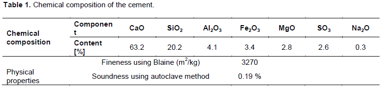
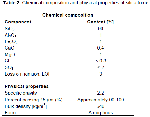
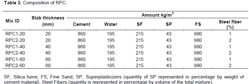
The RPC considered here is prepared by the following ingredients: ASTM Type I Portland cement produced in Iraq of (TASLUJA) and taken from local markets; natural sand (0-2.0 mm, with a specific gravity of 2.7); a polycarboxylate-based superplasticizer (SP) SikaViscocrete-5930 and brass-coated steel micro-fibers, with a density of 7850 kg/m³, a length of 13 mm, a diameter of 0.18 mm and an l/d ratio of 72. The cross section of the fiber was circular. The chemical composition and physical properties of the cement and silica fume used are presented in Tables 1 and 2 respectively. The composition of RPC with a water to cement ratio (W/C) of 0.18 used in this study is given in Table 3.
Concrete mixing and properties
All the dry constituents of the RPC were batched by an electronic balance. The dry constituents were first mixed for about 4 min at low and high speed in Pan Mixer. Water and superplasticizer were added gradually and re-mixed for about 5 min at high speed until the materials were uniformly mixed. Lastly the fibers were introduced, dispersed uniformly by using a sieve and additional mixing was applied for about 2 min.
The mixing procedures proved satisfactory in that the dispersion of fibers were found to be uniform and there was no evidence of fiber balling. Flow table tests, as per ASTM C230, were undertaken before casting of the specimens to assure that the fiber reinforced concrete mix had achieved a flow between 160 and 250 mm for the selected mix.
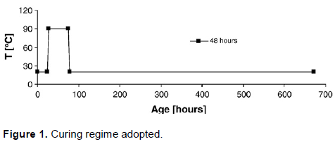
The hardened specimens were demolded after 24 h, and cured by two procedures were applied. The first procedure included demoulding of the specimens 24 h after casting and their subsequent storage at 95% RH and 25°C. The second procedure included a heat treatment at 90°C which was followed by storage at 95% RH. Based on an extensive study whose results are described by Cwirzen (2007), the heat treatment started after 24 h from casting and lasted 48 h. The curing protocol adopted in this study is indicated in Figure 1. Heating rate of treatment was 12°C /h. This extended (48 h) high temperature (90°C) heat treatment which is different from conventional curing process was preferred due to the high amount of reactive cementitious materials in RPC. Studies showed that high mechanical properties can be achieved under these conditions at early ages. Heat treatment densified the microstructure of the RPC matrix. The specimens, which were subjected to heat treatment, were kept in laboratory conditions for cooling before testing in this study.
Test specimens
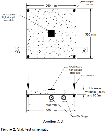
In the present work, twelve RPC square slabs with full side length of 560 mm, and center to center span between supports of 500 mm with a different thickness of 20, 40 and 60 mm. The slab was simply supported along its four edges and loaded by a central steel plate of dimension 70×70×25 mm. Three experimental variables are investigated in this study to show their effects on the behavior of the reinforced reactive powder concrete slab specimens. These variables are percentage of steel fibers, types of curing and thickness of the RPC slab.
Concrete tests
The compressive strength test was carried out according to B.S: 1881: part 116 (B.S. 1881:1983) using a digital testing machine with a capacity of (2000 kN). For each measurement, a set of three specimens 5×5×5 cm3 was used. The tests were performed at the following ages: 1, 7 and 28 days. The loading was applied at a rate of 0.9 kN s-1. Splitting tensile strength has been determined by testing six standard cylinders of 100×200 mm for every mix depending on ASTM C496-04 specification (ASTM C 496/C 496M, 2005). The cylinders were cast, demoulded and cured in a similar way as for slab specimens. Prismatic specimens (50×50×300 mm) were used to determine the flexural behaviors in conformity with ASTM C78-02 (ASTM C78-02, 2002). Each prism was simply supported and subjected to a two point loading using an electrical testing machine with a capacity of (2000 kN). The tests were performed at the age of 28 days. Elastic modulus test was carried out on 100×200 mm cylindrical specimens. The 40% of ultimate compressive strength of concrete specimen was applied on the concrete cylinders to perform the elastic modulus test as specified by ASTM C469 (ASTM C469-02, 2002). In each taken slab, each data presented here are the average of test results of the three specimens.
Testing procedure
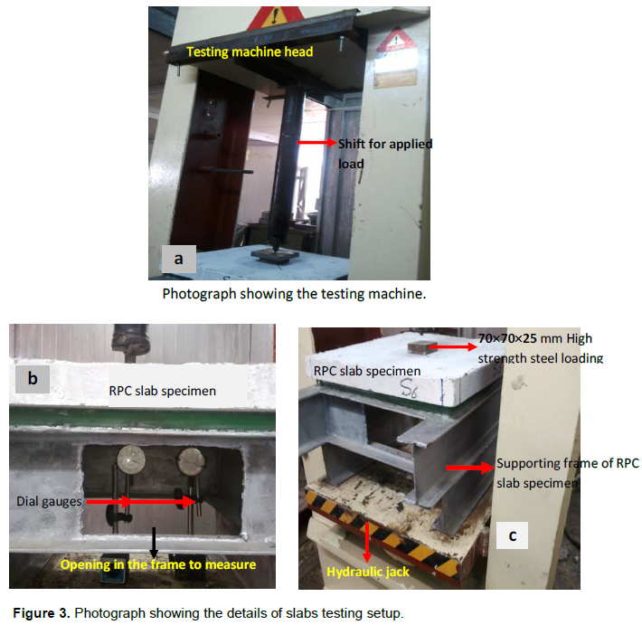
Before the testing day, the slab was taken out from the curing container, cleaned and painted with white paint on both surfaces, to achieve clear visibility of cracks during testing. The slab was labeled and carefully placed along the edges on simple supports. The point load was applied at the center of the slab and the dial gauges were positioned in their places, so that a precise setup of the testing equipment was achieved. Figure 2 shows the testing of slab specimens mentioned above. The slab specimens were tested used a hydraulic testing machine with a capacity of (20000 kN) available in the structural Laboratory in Civil Engineering Department; College of Engineering is illustrated in Figure 3a.
The load was applied gradually in increments of 4 kN until failure occurs. This amount of incremental loading allows sufficient number of loads and corresponding value of deflections to be taken during the test which gave a good picture for the structural behavior of the slab specimens. Tow dial gauges having accuracy of 0.001 mm per deviation and capacity of 10 mm and a maximum sensor length of 50 mm were used to measure the mid-span deflection and 125 mm from mid-span of slab specimen see Figure 3b and c).
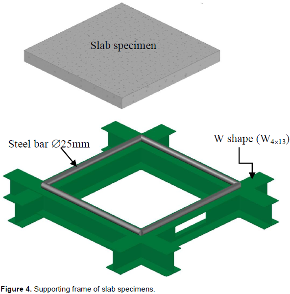
It is worth pointing out here that the 560 mm length of the square slabs of the present investigation was larger than the maximum space of 450 mm offered by the MFL system testing machine. Therefore a special supporting frame was manufactured and used inside the testing machine, as shown in Figure 4, to provide the required span of the slab. This supporting frame was made using four steel beams of the type W-shape (W4×13) welded and arranged to form a square shape. Each of which had a 25 mm steel bar welded on its top face to provide a simple support for the slab edge.
RESULTS AND DISCUSSION
Engineering properties of RPC
The engineering properties of RPC under two different curing conditions are shown in Table 4. The highest measured 28-day compressive strength values for the mixes of the heat-treated and non-heat-treated specimens are shown in Figure 5. The highest compressive strength value of 194.6 MPa was obtained in case of the heat-treatment incorporating a volume fraction of 2% steel fibers. On the other hand, the 28-day compressive strength value of the non-heat-specimens reached 173 MPa and was measured in mix RPC2/N. Because the pozzolanic reaction resulting from the ingredients of silica fume, in the RPC mixture will be activated energetically by the high temperature and moisture of curing. This pozzolanic reaction causes adenser microstructure of C-S-H cement hydrate and results in a faster development of strength gain.
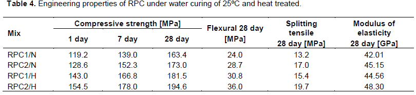
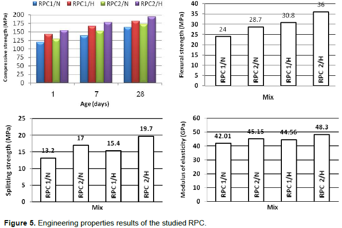
The splliting tensile strength of RPC for all mixes is much lower than the compressive strength, because of the ease with cracks which propagate under tensile loading, and is usually not considered in design. However, it is an important property, since cracking in concrete is most generally due to the tensile stresses that occur under load, or due to environmental changes. Referring to Table 4, the splitting tensile strength of RPC cylinders can be increased up to (27.9 and 28.8%) as the micro fine steel fibers volume ratio increases from 1 to 2% for heat-treated and non-heat-treated RPC mixes respectively. This is due to the fact that fibers bridge tensile cracks and retard their propagation (Graybeal and Hartman, 2002). The steel fibers improve the characteristics of cement-based matrices in the hardened state; they are able to bridge cracks, transmit stress across a crack and counteract crack growth (Mahdi, 2009). As shown in Figure 5, the presence of micro steel fibers influenced the flexural strength of the studied mixes. The results showed an increase of the flexural strength from 24 to 28 MPa after the addition of 2% of steel fibers and up to 36 MPa in the case of the heat-treated mixes.
The splitting tensile strength is related to the failure mechanism in tension due to the concentration of stresses at the tip of an elliptical crack. According to this theory the tensile strength will increase with shorter cracks, higher total modulus of elasticity and lower porosity (Penttala et al., 1995). The modulus itself is influenced by three concrete phases; binder matrix, aggregates and ITZ. Consequently, the wide and porous ITZ or weak and cracked aggregates will lower the tensile strength. Furthermore, the larger maximum aggregate size the greater their ultimate influence on the mechanical properties. Thus, it can be concluded that the main function of the short steel fibers is to stop the opening and the propagation of the microcracks. A negligible increase of the flexural strength of the RPC after the addition of steel fibers can be explained by the unfavorable combination of at least two effects. The first effect is due to de-bonding of the binder matrix from the aggregate surface in tension. The second is due to described possible increase of the internal stresses caused by the presence of micro cracked aggregates. In order to overcome these effects significantly, higher amount of the steel fibers would have to be incorporated into the binder matrix.
With respect to these curves, it can be noticed that the highest value of the modulus of elasticity of 48.3 GPa was measured in the RPC2/H mix. The lowest value of the modulus of elasticity which equaled 42.01 GPa was measured in case of the RPC1/N mix. The heat treatment did not have significant effect on the measured values.
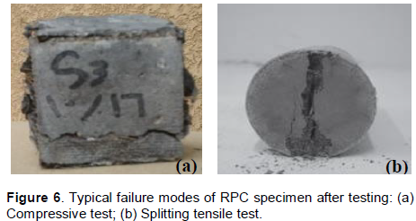
Typical failure modes of RPC specimens from the compressive and splitting tensile tests are shown in Figure 6a and b respectively. It is noted that, unlike the normal weight concrete specimens with the failure modes of either in crushed state or two separated pieces, these failed RPC specimens are still kept together by the steel fibers.
First crack load, ultimate load and load versus deflection for slab specimens
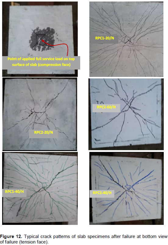
In this study, twelve slabs were tested. The test results of these slabs included the first crack load, peak load, load- deflection curves and crack pattern as well as modes of failure data are presented in Table 5. In all slabs, flexure failure occurred and the cracks initially formed near the center of the slab on the tension face and radiated to the edges. As loading continued, the cracks along the diagonals on the tension face widened and extended with additional cracks forming at the central region of the tension face. At higher loads, further flexural cracks were formed progressively and widened as the loading increases. As the flexural cracks widened, the fiber pullout reached its final stages and the slab failed. The test revealed that the increasing micro steel fibers content usually leads to an increase in the peak load and ultimate deflection with delays the propagation of cracks and controls their growth in the slab as shown in Figure 7. This can be attributed to the fact that the efficiency of steel fibers in arresting the propagation and controlling the growth of cracks within the slab, and hence, steel fibers maintain the slab integrity throughout the post cracking stages of behavior. The slab, hence could withstand greater loads and deflection before failure. It is evident from Table 5 that the deflection at ultimate load is considerably increased by the presence of steel fibers and using heat treated.
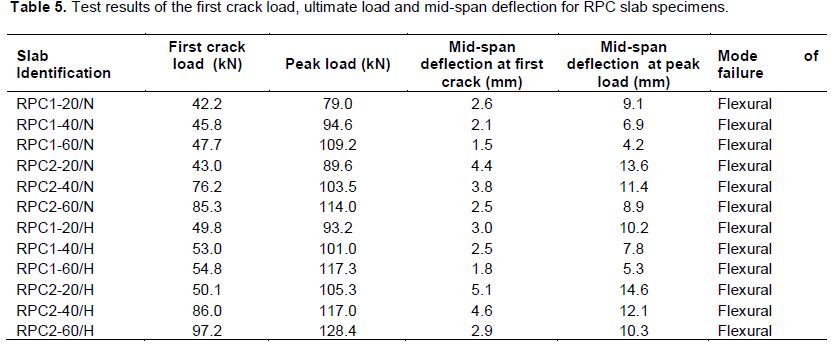
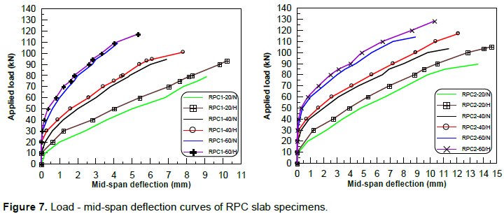
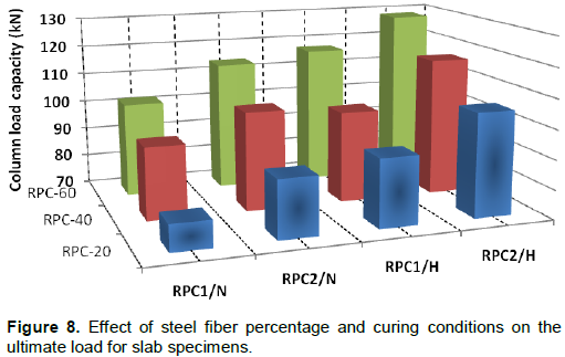
Figure 8 shows clearly that the fiber volume fraction has a significant effect on the ultimate load carrying capacity of slab specimens. Heat-treatment curing seems very effective ways to increase the peak load of RPC slab specimens. This can be attributed to the improvement of hydration process under these curing regimes. The RPC slabs under heat-treatment at volume fraction (1 and 2%) results in an increase in the mid-span deflection at peak load of 26.2 and 15.7%, respectively in compared to that of non-heat slabs.
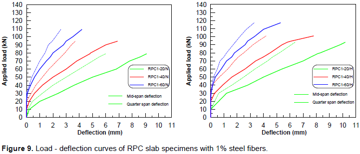
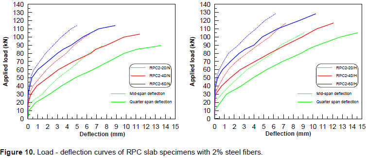
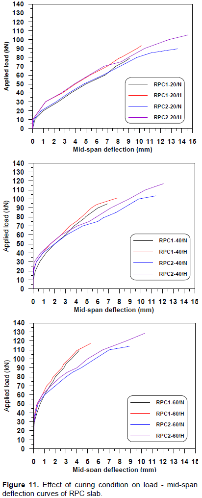
The load versus deflection relationship of slab specimens is presented in Figures 9 to 11. Deflections of these slab specimens were measured by using two dial gages, one located at the center of the slab and the other at 125 mm away from slab center. In all RPC slab specimens, the deflections were recorded immediately after the application of the load. At peak load, the rate of increase in deflection was so fast that no reliable deflection value could be measured. Accordingly, all load-deflection curves were terminated at their peak load value. In addition, it can be concluded that the increase in the percentage of fibers with using heat-treatment increases the load carrying capacity and increases the deflection in slab specimens. This can be attributed to the fact that the efficiency of steel fibers in arresting the propagation and controlling the growth of cracks within the slab, and hence, the steel fibers maintain the slab integrity throughout the post cracking stages of behavior. The slab, hence could withstand greater loads and deflection before failure. For all slabs that fibers tend to align in the direction of the flow of the material and also with the formwork. For RPC mixes containing 1% micro steel fibers, it is obvious from the results that the percentage of peak load increases when the thickness of slab specimens increases from 20 to 60 mm, the peak load increased to 38.2 and 25.9% for non-heat specimens and heat-treated respectively and mixes containing 1% micro steel fibers. This result ensures that the slab thickness has a significant effect on shear strength of RPC slabs under heat or non-heat-treated. Also for the same mixes, it can be noticed that in increasing the slab thickness, the deflection at peak load shows significant decreases from 9.1 mm (RPC1-20/N) to 4.2 mm (RPC1-60/N) and 10.2 mm (RPC1-20/H) to 5.3 mm (RPC1-60/H) for non-heat treated and heat-treated respectively.
It is clear from the above Table that the thin slab with 20 mm thickness seems clearer in ductility behavior in comparison to the slab specimens. From the test results, it is clear that the role of slab thickness on the behavior of slab specimens, the values of mid-span deflection of slabs increases with decreasing of slab thickness. This indicates that the use of RPC allows for smaller, thinner, lighter sections to be designed while strength is still maintained or even improved and taking advantage by minimizing material usage and cost in addition to reducing the weight of slabs. The appearance of the RPC slab specimens after failure is shown in Figure 12.
CONCLUSIONS
CONFLICT OF INTEREST
REFERENCES
|
Adeline R, Cheyrezy M (1998). The Sherbrooke Foot- bridge: the First RPC Structure. FIP 98, Amsterdam, May.
|
|
|
|
|
|
ASTM C 496/C 496M (2005). Standard Test Method for Splitting Tensile Strength of Cylindrical Concrete Specimens. Vol. 04.02.
|
|
|
|
|
|
ASTM C78-02 (2002). Standard Test Method for Flexural Strength of Hydraulic-Cement Mortars. Vol. 04(02):6.
|
|
|
|
|
|
ASTM C469-02 (2002). Standard Test Method for Static Modulus of Elasticity and Poisson's Ratio of Concrete in Compression.
|
|
|
|
|
|
BS 1881-116 (1983). Method of Determination of Compressive Strength of Concrete Cubes. British Standards Institution, P. 3.
|
|
|
|
|
|
|
|
|
|
|
|
Etienne D, Causse M, Behloul M (2001). Design and Building of Seoul Peace Footbridge. Third International Arch Bridge Conference, September. Paris, pp. 865-876.
|
|
|
|
|
|
Graybeal B, Hartman J (2002). Ultra high performance concrete material properties. Transportation Research Board Conference, USA, November 15:1-14.
|
|
|
|
|
|
Harris DK (2004). Characterization of Punching Shear Capacity of Thin UHPC Plates. Faculty of the Virginia Polytechnic Institute and State University.
|
|
|
|
|
|
Mahdi BS (2009). Properties of self compacted reactive powder concrete exposed to saline solution. Ph.D. Thesis, Building and Construction Engineering Department, University of Technology, Baghdad, P. 223.
|
|
|
|
|
|
Mindess S, Young JF, Darwin D (2003). Concrete. 2nd Ed., Prentice Hall.
|
|
|
|
|
|
Penttala V, Hannonen P, Jarvinen M Komonen J (1995). Effects of aggregates and microfillers on the flexural properties of concrete. Report 5, Helsinki University of Technology, Espoo, P. 113.
|
|
|
|
|
|
Richard P, Cheyrezy M (1994). Reactive Powder Concretes With High Ductility and 200–800 MPa Compressive Strength. ACI Spring Convention, San Francisco, April.
|
|
|
|
|
|
|
|
|
|
|
|
Rebentrost M, Cavill B (2006). Reactive Powder Concrete Bridges. 6th Austroads Bridge Conferences, 12–15 September, Perth, Australia.
|
|
|
|
|
|
Schachinger I, Hilbig H, Stengel T (2008). Effect of Curing Temperature at an Early Age on Long Term Strength Development of UHPC. 2nd International Symposium on Ultra High Performance Concrete, Kassel, 05-07 March. pp. 205-212.
|
|
Copyright © 2024 Author(s) retain the copyright of this article.
This article is published under the terms of the Creative Commons Attribution License 4.0


