The purpose of this paper is to present a technique of variable cross section conformal cooling channels (VCCC) to compare the cooling effect of moulds with equal section channel experimentally. The influence of the size structure parameters of the variable cross section conformal cooling channel on heat transfer is studied. It is found that the ratio of D/d=1.4 has the best effect of enhanced heat transfer. To determine the better heat transfer effect of variable cross section channel,this paper studies the influence of variable cross section channel and traditional equal section channel on heat transfer and takes temperature distribution, pressure drop and water velocity as evaluation indexes. In addition, in order to further discuss the effect of the conformal cooling channel structure, the influence of the opposite direction channel arrangement and the same direction arrangement on the heat transfer is studied. It is found that the adjacent channel of the opposite direction arrangement has better heat transfer effect and cooling uniformity.
During the injection molding process, the melt plastic injected into the mold cavity is rapidly cooled from 200 ~ 300 to 60 ~ 80°C in mould opening stage, and about 95% of the heat released by the cooling is taken away by the fluid medium (Ilyas et al., 2010). The cooling system controls the temperature change of the mold and the distribution of the temperature field. The temperature of the mold directly affects the smoothness of the molding process. The temperature field distribution at different times is related to the surface quality and dimensional accuracy of the final product. This is the main thing that affects the physical and mechanical properties of the product. In addition, the speed of temperature changes also affects the molding process of energy consumption and product molding cycle. Therefore, the cooling system research has been one of the key areas of injection molding. In order to solve the problem of uniform cooling, the researchers proposed the conformal cooling water channel. Conformal cooling water channel refers to the cooling water channel in which the injection cavity shape changes, and its mold cavity surface distance is always consistent. Wang et al. (2011) present an automatic method for designing conformal cooling circuits, which is an essential component that directly affects the quality and timing for products fabricated by rapid tooling. Nogueira et al. (2010) report in a case study involving the use of conformal cooling channels obtained in wax by 3D-impression.
Mohamed et al. (2013) present a simulation study of different types of cooling channels in an injection molded plastic part and compare the performance in terms of time to ejection temperature, shrinkage, temperature profile, and part warpage to determine which configuration is more appropriate to provide uniform cooling with minimum cycle time. Ilyas et al. (2010) present new results on the impact of conformal cooling on the productivity and energy efficiency of injection moulding, and on the durability of the indirect SLS material in injection moulding applications. A novel “cut-out volume” technique for powder clearing is also presented, along with a set of design rules to support further application of the work. Marques et al. (2015) proposed two conformal cooling designs: i) parallel circuit; ii) serial circuit. In order to understand the cooling effect of different cascading cooling solutions using the geometry of the plastic part as a workpiece, Wang et al. (2014) developed a new rapid die heating and cooling method and established a model to evaluate the effectiveness of the new rapid die heating and cooling method. This paper combines the characteristics of conformal cooling and enhanced heat transfer (Wang et al., 2011; Chen et al., 2014; Li and Liu, 2011; Xiao, 2006; Xue et al., 2011; Huang et al., 2005, 2006; Zhang et al., 2008, 2010). The method of variable cross section reinforced heat transfer is proposed, and the water pressure drop, velocity and temperature field distribution of constant-section curve channel and variable cross-section curve channel are compared and analyzed by simulation software.
Design of heat transfer enhancement of conformal channel
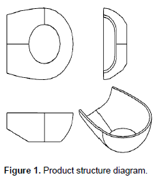
An electronic plastic product is studied in this paper, as shown in Figure 1. The product shape is a surface structure with a thickness of 2.9 mm and the material is ABS. Its physical properties are shown in Table 1. The forming die in this paper adopts a mold and cavity.

Equal section conformal cooling channel
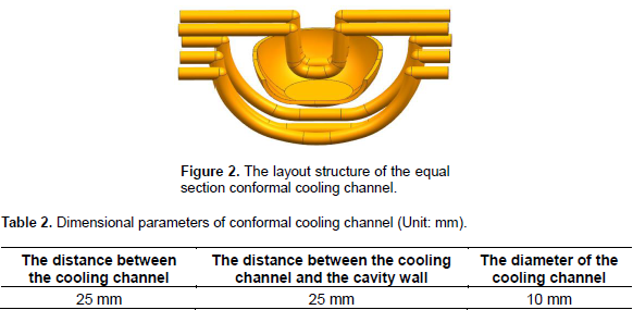
The traditional conformal cooling channel is equal section. And its layout is shown in Figure 2, according to the structural characteristics of the product and mold. The size parameters of the channel are shown in Table 2.
Variable cross section conformal cooling channel
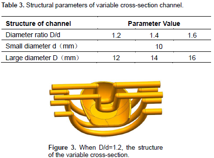
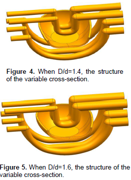
The design of conformal cooling channel with the variable cross section can alleviate the problem of rising temperatures, uneven temperature distribution and residual thermal stress in the mold to a certain extent. The ratio of the best value range of the variable cross-section of the large diameter D and small diameter d is 1.1 to 1.7 (Lei and Yunxia, 2011). This paper selects three D/d ratio. In this paper, three kinds of D / d ratios are selected. The structural parameters of the variable cross-section channel are shown in Table 3, and the cross-sectional size of the cooling channel changes linearly along the flow direction. When D/d=1.2, its geometry is as shown in Figure 3; when D/d=1.4, its geometry is as shown in Figure 4; when D/d=1.6, its geometry is as shown in Figure 5.
Grid independency
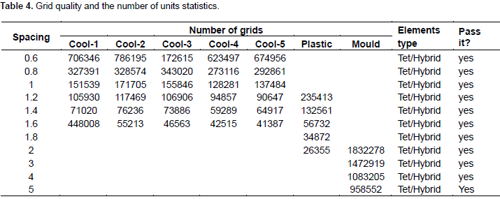
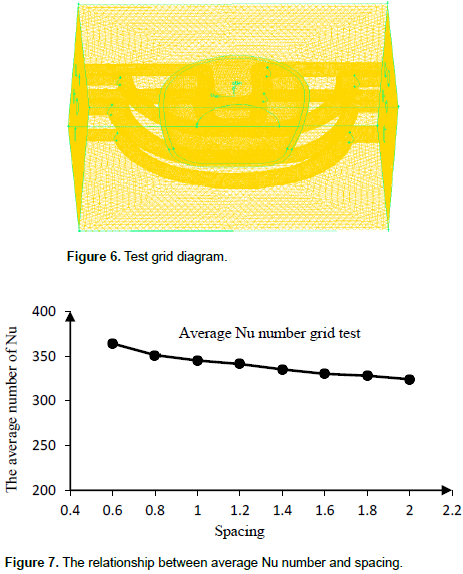
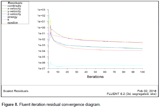
In this paper, grid testing and final meshing are all conducted in Gambit, using Tet/Hybrid meshing. Taking one of the models as the grid test object, the inlet velocity u = 0.8 m/s, the inlet water temperature Ti = 298 K, and the outlet relative pressure P2 = 0 Pa are the test conditions. In this paper, we choose the average Nu reference and find out the suitable meshing method based on grid quality and unit number. The test results are as follows: Table 4 shows the grid quality and unit quantity statistics. Figure 6 shows the test grid chart. Figure 7 shows the line chart of the change of average Nu number with spacing.
Outcomes analysis
(1) In Table 4, as the cell size decreases, the number of cells and number of nodes increase sharply, while the average grid quality improves.
(2) In Figure 6, as the unit spacing increases, the average number of Nu gradually decreases. After spacing = 1, the trend of change tends to gradually decrease and gradually balances.
(3) From comprehensive consideration, the final cooling channel grid spacing is 1 mm, product grid spacing is 1.6 mm, and the mold grid spacing is 4 mm.
Residual convergence
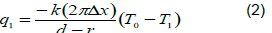
A residual in numerical simulation is shown in Figure 8. The residuals of the variables involved in the iterative calculation are used as the basis for the numerical simulation to determine the convergence. It is plotted for continuity, x-velocity, y-velocity, z-velocity, Rayleigh kinetic energy (k) and Rayleigh dissipation factor (epsilon). The residual is in the order of 10-3; when the residual value is less than 10-3, the above reference is considered to converge and the residual energy control is in the order of 10-6.
The steps of solution
In this paper, the simulated fluid is incompressible steady-state flow, and the separation solver is selected. The three-dimensional steady-state calculation is used. The operating environment is based on a standard environmental pressure, and the standard k-ε model is chosen without considering gravity. At the same time, the wall processing method for enhancing the wall function is adopted. The steps for fluent (Tan, 2002) to solve the problem are shown in Figure 9. The boundary conditions for solving the model are shown as follows:
The inlet velocity of the inlet boundary condition is 0.5 to 1 m/s, and the water temperature is 25°C
(2) The export boundary condition is set to the pressure outlet;
(3) The wall surface of the channel and the mold wall are set to couple the wall condition, and the wall of the product and cavity are also arranged in a coupled wall condition.
Heat transfer model
The heat transfer model is shown in Equation 1.
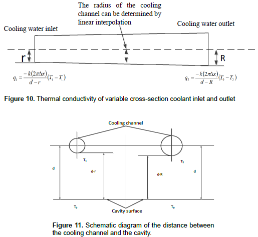
The size of the surface heat transfer coefficient is related to many factors in the heat transfer process, including the physical properties of the fluid and the heat transfer surface size and layout, while the flow rate is closely related. In order to ensure uniform heat transfer from the cavity surface to the cooling channel, the Fourier heat transfer law was used to find the relationship between the inlet radius r and the exit radius R. According to the Fourier equation, the heat conduction rate of the radius r can be expressed as:
Where, x is the length of the cooling channel, T0 (T0> T2> Ti) is the temperature of the cavity surface, and T1 is the temperature of the cooling channel near the inlet. The outlet heat transfer rate of radius R can be expressed as:
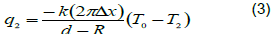
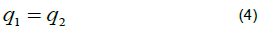
Where, T2 is the temperature of the cooling water channel near the outlet. The thermal conductivity of the inlet and outlet of the variable cross-section cooling water is shown in Figure 10. In order to achieve a uniform heat transfer rate through the cooling waterway at any location on the cavity surface, the heat transfer rate q1 near the inlet must be the same as the outlet q2. The heat transfer and outlet heat conduction along the entrance of the cooling channel are constant:
In Figure 11, the mathematical formula between the inlet radius and the exit radius of the variable cross-section channel can be found in Equations 5 to 7.
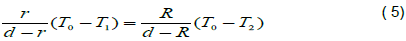
Where d is the distance between the cooling waterway center and the cavity surface, To is the temperature of the mold surface, T1 is the temperature of the cooling water channel near the cooling water inlet, and T2 is the temperature of the cooling water channel near the cooling water outlet.
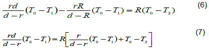
Therefore, the size of the cooling channel radius R near the coolant outlet can be derived in Equation 8:
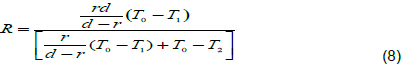
Variable cross-section channel provides better cooling uniformity than conventional channel. By increasing the surface contact area near the outlet and increasing the volume of cooling water flow, it can take more heat from the plastic melt. In theory, the variable cross-section of the channel can compensate for the inlet-outlet coolant temperature difference by using a large radius of the cooling channel near the outlet and at the exit. In practice, variable cross-section channel can be designed and analyzed with CAD/CAM systems, and injection molds can be manufactured using fast tools or injection molds.
Temperature field distribution of variable cross-section cooling products
The temperature field distribution of the variable cross-section conformal cooling product is shown in Figure 12. From Figures 12 and 13, it can be seen that the temperature field distribution is basically uniform and the distribution is basically the same. In Figure 12a, the maximum local product temperature is 325 K, the average temperature is 313.5 K, the minimum temperature of plastic products is 302 K, the temperature difference is relatively small. In Figure 12b, it can be seen from the temperature cloud diagram that the maximum temperature of Figure b is lower than that of Figure a; the maximum temperature of the product is 321 K, the lowest temperature is 302 K, the higher temperature is distributed at the edge and the middle of the product. The temperature is 312.4 K. The temperature in Figure 12c is significantly higher than that in Figure 12a and 12b. And the local maximum temperature of this product is 325 K; the lowest temperature is 304 K. The temperature difference between maximum temperature and the minimum temperature is relatively large, and the temperature difference is 11 K. In the product section shown in Figure 13, red parts represent the highest temperature in the temperature distribution profile. It can be seen that the temperatures shown in Figure 14a and c are significantly higher than that in Figure 14b.
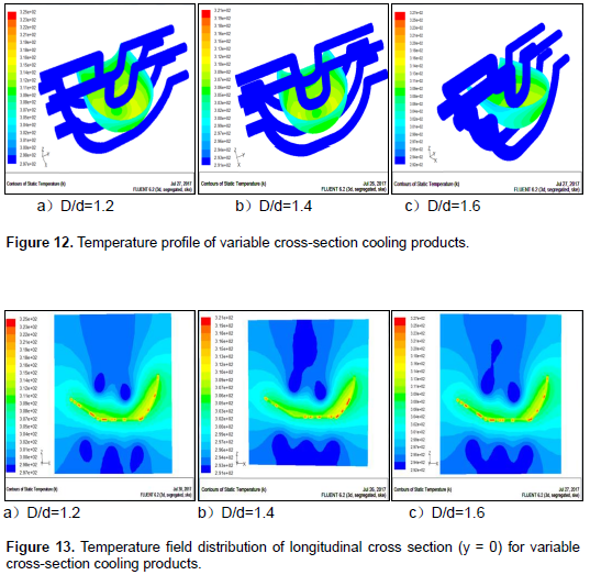
Therefore, we find that when D/d = 1.4, the hot cooling effect is the best. From the heat transfer formula, the heat transfer Q is positively correlated with the heat transfer area A and the surface heat transfer coefficient h. In the three structures mentioned above, the heat transfer area A increases as the diameter of the outlet increases. Therefore, in case where other conditions remain constant, the heat transfer Q also increases. The surface heat transfer coefficient h is positively correlated with the velocity of the water (Huang et al., 2005; Wang et al., 2014). When D/d = 1.2, a small heat transfer area and a higher flow rate lead to poor heat transfer. When D / d = 1.6, although the heat transfer area increases, the water flow rate decreases a lot, resulting in poor heat transfer effect. Considering these two reasons, we found that better heat transfer effects can be obtained when D/d= 1.4.
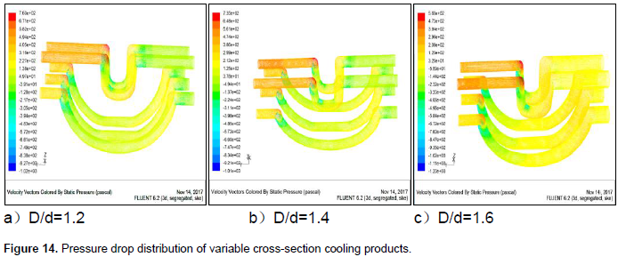
Pressure drop distribution of variable cross-section conformal cooling products
The pressure drop distribution of the product with variable cross-section conformal cooling is shown in Figure 15. It shown in Figure 14 that the maximum pressure drop of these three structures is reduced from 760 to 560 Pa. The flow of water from the inlet to the outlet end of the pressure is continuously reduced. The cooling water flows in the pipeline and the flow of water in the channel is affected by the channel structure. The speed of the fluid in the channel will also have a relatively large change. When the fluid flows in the tube, the pressure is reduced due to energy loss which is caused by the flow of fluid to overcome the internal friction and turbulence when the fluid particles collide with each other. The exchange of momentum is manifested in the fluid flow before and after the pressure difference, that is, pressure drop. The pressure difference is generated before and after the fluid flow. When the fluid flows through the channel, the boundary layer is constantly destroyed. So the heat transfer effect is enhanced. But at the same time, the pressure drop increases very quickly. Injection mold cooling channels of variable cross-section can significantly improve heat transfer enhancement effect.
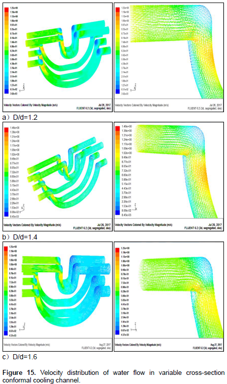
Variable cross section conformal cooling channel velocity vector cloud
The velocity distribution of the variable cross- section conformal cooling channel is shown in Figure 15. The three velocity profiles with different diameter ratios are shown above, including the distribution of the overall and partial channel velocity. The same is that the flow rate of the water flow through the bent portion is relatively high; But in the bend of the channel, There will also be a swirl of water in some parts. There are also parts of the water that are almost stationary. It can be seen from the above velocity vector cloud diagram that when D/d=1.2, the variable flow rate is 1.25 m/s with the flow velocity in the channel, but the velocity is basically kept at 0.65m/s. When D/d =1.4, reflected from the cloud, the flow of water flow through the curved part of the flow rate is relatively high, about 1.13~1.22 m/s. By the cloud shows the outlet speed of 0.515 m/s, the speed difference between inlet and outlet is about 0.3m/s; when D/d =1.6, compared with the velocity diagram of the previous two structural parameters, the velocity of the water flow decreases obviously. The velocity of the inlet is 0.8 m/s, and the maximum water velocity in the water flow is about 1.0m/s, but the minimum outlet speed is 0.25 m/s, the speed difference between inlet and outlet is about 0.55 m/s. Compared with the previous two cases, the speed difference is greater. In summary, the reasons for the formation of the velocity distribution and the pressure drop distribution are consistent, and the pressure drop in the channel is closely related to the velocity distribution. According to the temperature field distribution, pressure drop distribution and velocity distribution, it is shown that the heat transfer effect at D/d=1.4 is superior to that of other structures.
Analysis of the results of equal cross section and variable cross section
For the above three structures, the different diameter ratios are shown above, including the distribution of the overall and partial channel velocity. The flow rate of the water flow through the bent portion is relatively high. But in the bend of the channel, there will also be a swirl of water in some parts. There are also parts of the water that are almost stationary. It can be seen from the above velocity vector cloud diagram that when D/d=1.2, the variable flow rate is 1.25 m/s with the flow velocity in the channel, but the velocity is basically kept at 0.65 m/s. When D/d =1.4, reflected from the cloud, the flow of water through the curved part of the flow rate is relatively high, about 1.13 to 1.22 m/s. The cloud shows that the outlet speed of 0.515m/s, the speed difference between inlet and outlet is about 0.3 m/s; when D/d =1.6, compared with the velocity diagram of the previous two structural parameters, the velocity of the water flow decreases obviously. The velocity of the inlet is 0.8 m/s, and the maximum water velocity in the water flow is about 1.0 m/s; but the minimum outlet speed is 0.25 m/s; the speed difference between inlet and outlet is about 0.55 m/s.
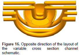
Compared to the previous two cases, the speed difference is greater. In summary, the reasons for the formation of the velocity distribution and the pressure drop distribution are consistent, and the pressure drop in the channel is closely related to the velocity distribution. According to the temperature field distribution, pressure drop distribution and velocity distribution, it is shown that the heat transfer effect at D/d=1.4 is superior to that of other structures. According to the structural diagram, the coolant enters from the left end and flows from the right end. The diameter of the left pipe is small and the diameter of the right pipe is larger. In order to reduce the non-uniformity cooling caused by the asymmetry of the structure, the enhanced heat transfer structure of the opposite arrangement of two adjacent channels is adopted, and its structure is shown in Figure 16. By comparing the variable cross-section channels in different arrangement directions under the same size conditions, it is possible to determine which type of watercourse in the same size has a better heat transfer effect.
The temperature cloud of equal cross section and variable cross section with comformal channel
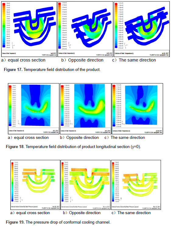
Through the analysis of the product temperature of the variable cross-section channel injection mold with different parameters, the heat transfer and cooling effect of the injection mold of the variable cross section water channel is the best when the structural parameter is D/d = 1.4; but to find out which has a better cooling effect between the same direction and the opposite arrangement of the variable cross section watercourse, the cross-section channel and the optimized cross-section are simulated and the temperature field cloud image is obtained, as shown in Figure 17. As shown in Figures 17 and 18, from the temperature distribution, we can see that the overall temperature distribution is roughly the same and more uniform in these three enhanced heat transfer structures. As the channel is far from the tail of the product, there is insufficient cooling at the end of the product. So, it can be seen that the three enhancement heat transfer structures have a residual heat concentration. In Figure a, the maximum temperature of the enhanced channel water transfer is 336k, and the average temperature is 318.2 K; the lowest temperature is 305 K. In Figure 19b and c, the maximum temperature of the two variable cross-section channel mold products is 321 and 319 K respectively, and the average temperature is 309.7 and 312.3 K, respectively; the lowest temperatures are 304 and 306 K, respectively. After comparing the three temperature distributions, we found that the heat transfer effect of the diagonal channel in Figure b was the best, and the heat transfer effect was much higher than that of the cross section. Based on the results of the temperature field distribution, these three enhanced heat transfer structures are derived from the change of the internal structure of the channel due to the basic structure of the channel. Through the simulation analysis on fluent, and comparison with the actual theoretical analysis, it is concluded that the cross section of the channel is different, and different arrangement is important to strengthen the heat transfer.
Pressure drop of equal cross section and variable cross section
The pressure drop in the cooling channel is shown in Figure 19. The pressure of the water inlet is higher than the pressure of the water outlet. In Figure 19a, the pressure at the inlet is at most 1140 Pa and the outlet pressure is 217 Pa, so the pressure drop across the channel reaches 923 Pa. In Figure 19b, the inlet pressure is 748 Pa, the outlet pressure is 120 Pa, pressure drop of about 648 Pa can be obtained. In Figure 19c, the inlet pressure is 735 Pa, the outlet pressure is 212 Pa, and the pressure drop is about 523 Pa. From the pressure drop graph, we can see that the pressure drop in graph a is the largest, and the energy loss of the flow in the cooling stage is very large. However, the energy loss is different from that in Figure a. So, from the pressure drop, we can conclude that the heat transfer effect of the opposite arrangement and the opposite direction are close.
Flow velocity vector cloud of equal cross section and variable cross section
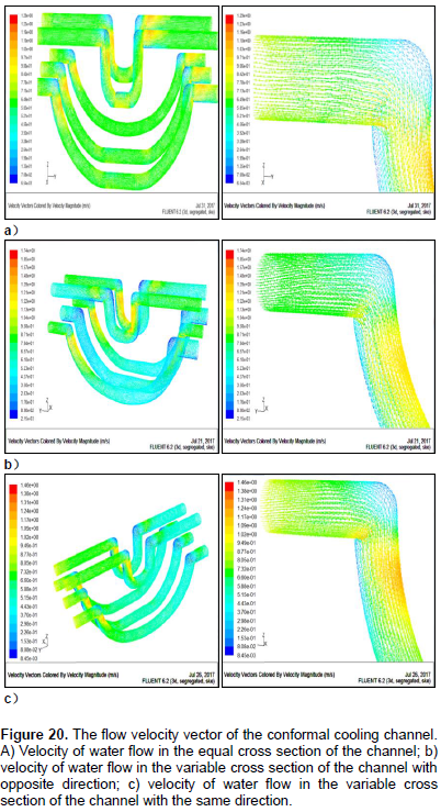
The simulated fluid flow velocity of the three channel structures is shown in Figure 20. As shown in Figure 20, the maximum flow rate in the equal cross section conformal channel is 1.29 m/s, and the lowest flow rate is 0.58 m/s; then the average flow speed of 0.64 m/s. The maximum water velocity in the two channels with variable crossings is 1.74 and 1.46 m/s, and the minimum flow rate is 0.52 and 0.44 m/s, respectively; the average water velocity is 0.68 and 0.66 m/s. The velocity of the water flow through the curved part of the three graphs is relatively high: 1.03, 1.13 and 0.94 m/s; but at the bend of the channel, the water velocity is almost zero, and in some places there will be a swirl of water. It can be seen that the variable cross section with different arrangement has better heat transfer effect, by comparing the water flow velocity and pressure drop in the channel.
Heat transfer and resistance performance test and analysis
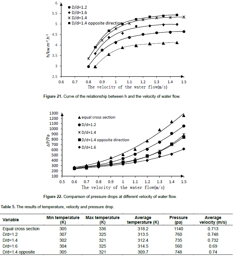
In this paper, the experimental study of heat transfer with variable cross-section channel and equal section channel is carried out. The experimental results are shown in Figure 21. Under the condition of the same water velocity, the enhanced heat transfer coefficient of the variable cross-section channel is obviously greater than that of the equivalent section channel. When the curve is flat, the heat transfer coefficient h of the variable section waterway with structural parameters (D/d=1.2, D/d=1.4, D/d=1.6, D/d=1.4) is increased by about 1.12, 1.29, 1.21 and 1.32 times than that of the equal cross-section channel, respectively. The relationship between pressure drop and flow rate is shown in Figure 22. It can be seen that the relationship between pressure drop and flow rate is approximately parabola, which is consistent with the theory. With the increase of flow velocity, it means the erosion of the wall surface and the increase of the resistance loss when the fluid flows through the water channel, so the pressure drop increases. With the increase of the channel diameter, which makes the effective flow area increases, the collision and friction between the fluid and the wall will cause the loss of resistance and increase the pressure drop. Therefore, when considering the method of heat transfer enhancement, one needs to consider the impact of both heat transfer and pressure loss. Based on the simulation analysis, the results of temperature, velocity and pressure drop are as shown in Table 5.
Variable cross section conformal cooling (VCCC) technology is a new type of cooling technology in the injection molding industry. In the mold manufacturing, VCCC design aspects and applications there is a lot of space for improvement. Whether it is in the normal injection molding process or a special molding process or cooling technology in the cascade one can get the desired results. However, the design process of the conformal cooling water channel is still cumbersome. Complex VCCC processing techniques and expensive production costs limit the application of conformal cooling technology. VCCC is still in continuous development and improvement of its stages. In this paper, the research is still too idealistic. The interference of hot runner, thimble, slider and other accessories on the CCC structure has not been considered. The actual production of plastic products is very numerous, most of which have complicated geometric shapes. The application of VCCC and specific examples is a daunting task. In view of the limitations of the plastic structure in this study, the design and analysis methods should be further amended in future studies.