Full Length Research Paper

ABSTRACT
This work aims to analyze the thermal deformation of a thermal shield laminated material under a uniform or one-sided heating of up to 600°C/min. The material is made of a fiberglass composite polymer material based on phenol-phormaldehyde matrix. This work describes the method used to study the kinetics of thermal deformation of the composite material at different heating rates and a high-temperature of gas flow (2500°C). The state of the stressed-deformed samples made of a reinforced plastic is computed and used to measure the expanded temperature of the materials under one-sided heating. It is shown that under both force and thermal loading, the linear dependence of the coefficient of thermal deformation ï¡Ð¢ on temperature, stresses in the sample developed to prevent the bending of free samples. For a bent sample, there is no stress gradient (ï„ï³ = 0) under increased heating rate of the loaded samples, leading to an increase in the stress gradient values. The data are compared with dilatometry results obtained at a uniform temperature field and heating rates of 20 to 1100°C.
Key words: Thermal shield, spacecraft, re-entry, composite material, high temperature, fiberglass, dilatometer.
INTRODUCTION
Thermal shield materials (TSMs) used for aircraft and aerospace technologies are classical examples of objects operating under extreme loads. Extreme conditions are defined by temperature, acting mechanical stresses, and also by the degree of chemical aggression of an external medium, intense radiation, abrasive erosion action etc.
In real conditions, thermal shield materials are exposed to thermal and chemical force simultaneously.
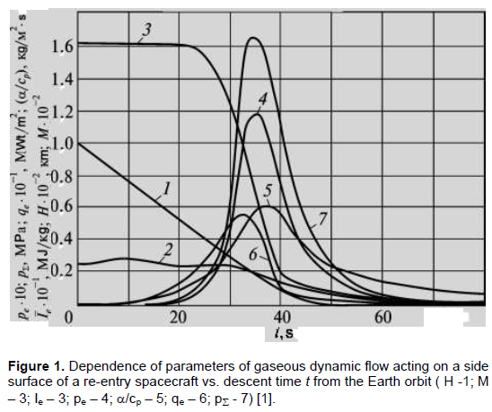
Changes in both the velocity and temperature of an incoming flow affect the thermal load on spacecraft characteristics.
Figure 1 shows the dependencies of parameters of high-temperature gas flow acting on the side surface of a re-entry spacecraft based on the descent time t from the earth orbit (Dimitrienko, 1997).
In heating process, both physical and chemical transformations occur in thermal shield laminates that radically change the structure, composition, and density of thermal shield materials.
Non-reversible changes of thermo-physical properties of the materials occur, such as decrease of density, increase of gas penetration, appearance of secondary porousness, change of thermal conductivity of materials in the direction of reinforcement and at right angles for all types of composites (Dzenis and Ponomaryov, 1989; Perepelkin, 1992).
The major types of surface or local destruction of the materials are as follows (Polezhaev and Jurevich, 1976; Tadmor and Gogos, 2006; Malkin, 1991; Khobragade and Deshmukh, 2005):
(1) Thermal destruction under the action of supercritical thermal flows due to change in the state of matter (melting, evaporation, sublimation);
(2) Mechanical destruction due to thermal stresses caused by thermal expansion (shrinkage) of thermal shield materials under physical and chemical transformations at high temperatures;
(3) Mechanical destruction in friction contact or while hitting moving solid objects quickly;
(4) Chemical destruction in reactions with aggressive media (liquid or gaseous).
The most important mechanism involved in the interaction between materials in ambient medium is the correspondence of experimental studies on the natural conditions of operation of a specific structure or model.
MATERIALS AND METHODS
To choose a thermal shield material for specific purposes, designers need to have laboratory setups that imitate conditions of material operation at maximal thermal loading to overcome the threshold of ablation of the surface of thermal shield materials.
To study the deformation and destruction of the models of thermal shield structures, special gaseous dynamics setups are created in the Institute for Problems of Strength (Kiev, Ukraine); they provide a possibility to test models of cylindrical, conical, prismatic shapes with length and width (diameter) of more than 300 mm.
A source of a high-temperature flow (up to 2500°C) was a gas jet of combustion products (kerosene in oxygen) in an aircraft-type camera (Voloshchenko et al., 1980).
Large-size models of a conical shape were used to study the kinetics of destruction and heat resistance of the thermal shield elements under erosive high-temperature and corrosive high-density gaseous flow (Figure 2) (Gracheva and Kharchenko, 2006).
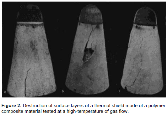
Cracks can develop themselves both at lower (a) and upper (b) butt, or they can go across the side surface of a shell (c). In any case, they develop along generatrix of a conical model of thermal shield laminate due to the action of stretching stresses. These in turn appear due to shrinkage of thermal deformations in the laminate under high-temperature heating.
The destruction can be caused by the accumulation of defects in the volume of the material that occurs in mechanical loading and thermal cycling under intense action of radiation.
Under extreme conditions, critical accumulation of defects may occur within a sufficiently short timeframe.
Glass plastics are traditional materials used for the thermal shield of the side surface of the re-entry spacecraft in the dense layers of the atmosphere.
The mechanism of thermal shield laminates is based on destroying the surface layer to create an operational thermal regime for either inner layers or a whole structure.
Thermo-mechanical destruction is a result of the action of thermal stresses that appear in a thermal shield laminate under intensive one-sided heating. Its distribution through the material thickness can be represented as (Lehnitsky, 1977):
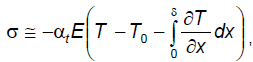
where d is the material thickness.
Direct measurements of the working layers of a thermal shield are practically impossible due to high temperatures and fast timeframe for all the processes. Therefore, to make conclusions on the working efficiency of thermal shield structures one can just rely on conditions close to real ones.
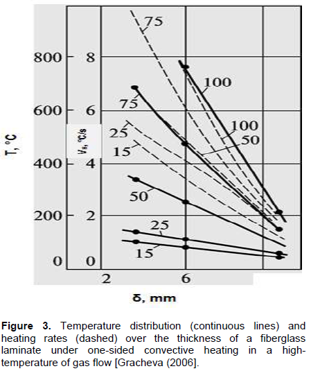
Figure 3 shows the results of thermometry of an outer layer of a thermal shield laminate in a weakly conical model (Figure 2); it was tested in a high-temperature jet of a gaseous dynamics setup that simulates operation of the structure under real conditions.
The reliability of composite materials destroyed by heat like thermal shield laminates is defined mainly by the character and magnitude of thermal deformations (TDs) due to increased temperature.
Thermal expansion analysis allows one to make conclusions about the working efficiency of thermal shield materials. Especially important are studies of linear thermal expansion coefficients conducted under real modeling conditions.
The goals of this study are (i) to determine the thermal expansion of a typical thermal shield laminate of a re-entry spacecraft, made of a fiberglass based on a polymer, under one-sided or uniform heating (ii) to analyze and compare the data obtained on the thermal expansion of a thermal shield material under varying types of delivering heating.
The dependence of temperature T of thermal shield laminate surface upon the time of descent of the apparatus in dense layers of the atmosphere is based on the physical modeling of natural environment for a thermal shield (temperature, heating and cooling rates, composition and pressure of a gaseous medium) (Table 1).
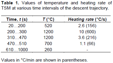
A trajectory of the spacecraft descent, divided into time sections, was used to study the thermal deformation of composite polymer thermal shield material with heating/cooling rates corresponding to real ones (Gracheva, 2019).
Here, the most reinforced plastics used on a thermo-reactive matrix are considered; their temperature deformations are changeable; they can shrink up to 5% or more in high-temperature heating. This, in certain cases, can destroy thermal shield laminate before depleting its thermal shield properties.
RESULTS AND DISCUSSION
Thermal deformation of a TSM under uniform heating
Fiberglass plastics are traditional materials used for the thermal shield material of the side surface of a re-entry spacecraft in the dense layers of the atmosphere.
Thermal shield material CCTF is a fiberglass, made by the method of hot pressing of silica fabric filled with phenol-phormaldehyde resin, a type of resol. Temperature deformation of CCTF was studied at the temperature range of 20 to 1100°C, with changing heating rates under homogeneous and one-sided thermal action. Deformation measurement was made by an automatic registering system using an opto-electronic method, excluding errors from the pressure of indentors on a softening sample (Marasin et al., 1991).
To control the temperature of the sample, a heating rate was brought about using platinum-rhodium thermocouples placed inside the sample.
Dilatometry was implemented in the air at heating rates of Vh equal to 10, 20, 25, 50, 75, and 100°C/min. Heating of the sample can be considered homogeneous. Thus, at a maximal level of heating rate (Vh = 100°C/min), the temperature gradient from the center to the sample surface was 3-7°C. After achieving the temperature T = 550-600°C, the readings of two thermocouples (in the center of the sample and on its surface) were practically the same. Due to the small temperature drops over the sample thickness, thermal stresses were not taken into account. Temperature stresses arising due to the inhomogeneity of properties of material in its cross-section were not considered as the samples were thin (Voloshchenko et al., 1980).
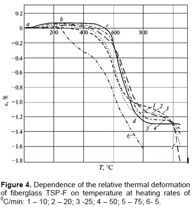
Figure 4 shows the curves of the relative thermal deformation of samples of 3 mm × 10 mm × 60 mm size, heated at different heating rates (with each given heating rate seven or eight samples were tested) (Tretyachenko and Gracheva, 1986). In a general case, the curve of the expansion-shrinkage of the reinforced plastic is characterized by the following processes:
(1) Expansion of the material up to the temperatures of solidification of a binder;
(2) Sample shrinkage caused by the decomposition of the polymer binder with gases getting out at this temperature, and also when coke starts forming;
(3) A simultaneously occurring shrinkage of the fiberglass in pyrolysis and a volume increase of the sample due to voids and cracks formed, on one hand, and thermal expansion of the coke formed, on the other hand;
(4) Completing mainly of pyrolysis.
It is seеn in Figure 4, with an increase in the heating rate, the expansion zone increases. The beginning of the shrinkage and intersection point of thermal deformation curves crossed by the temperature axis shifted towards the range of higher temperatures. The largest shrinkage is observed in the samples heated at the lowest rate.
Curves of thermal expansion of composite polymer materials destroyed by heat are poly-extreme and changeable. For such materials, analytic presentation of thermal deformation as a function of temperature is difficult due to a number of factors: first of all, a heating rate, which is connected to the time of occurring phase and structural transitions in the polymer matrix.
Analytical dependence of TD vs. temperature and heating time
Despite the rather complicated character of the curves of thermal deformation of composites based on destructive matrices, their analytic presentation is possible with statistical and regression analysis.
To determine the average values of deformation characteristics, confirm the shape of a generalized empirical dependence, and determine the necessary volume of data to build the function e=f(T), an algorithm was developed to automatically process the experimentally results obtained from the thermal deformation of fiberglass TSP-F based on temperature and time factors.
The code, implemented based on a least squares for an exponential, power, and polynomial dependencies, is a library of primary modules that allow one to smooth out experimentally obtained data.
In using polynomial dependence, not only coefficients of the polynome are defined but also its degree, which are the best for a given dependence in the sense of minimal discrepancy (Dreiper and Smith, 2016).
To compute unknown coefficients of the method of least squares, the Gauss method of solving linear algebraic equations was used. The process of solving it consists of steps of smoothening table values of given functions and formation of the matrix of coefficients obtained.
It is shown that among polynomials of 3rd-10th order used to build a generalized empirical dependence by the method of least squares, the best (in the sense of minimal discrepancy) happened to be polynomials of 4-5th degree of the type:

Figure 5 shows the computed data on thermal expansion of fiberglass TSP-F under heating rates of 25 and 75°C/min.
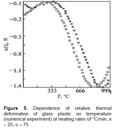
Results of a numerical experiment using established polynomial dependence showed relatively high coincidence with thermal deformation dependencies obtained under homogeneous heating at the rates of 10, 50, 75, 100°C/min (Figure 4).
Thermal deformation of TSM in one-sided heating
The dependencies of thermal deformation of a composite material are obtained in a homogeneous heating-through of the samples. Real operating conditions of high-temperature composites are characterized by a sharp non-homogeneity of temperatures over the thickness of a thermal shield laminate caused by intense heat flows directed inside the structure. To determine the dependence of thermal deformation of fiberglass on temperature and time in one-sided heating on a dilatometric setup, a series of experiments were performed under changing heating rates in the air.
As a model, a narrow sample was chosen; its thickness corresponded to the structure thickness, and its length exceeded the influence zones of edge effects. To model the influence of action of non-heated layers of the laminate into pyrolysis layers, the sample was loaded according to the scheme of bending from the side of a cooled surface (Figure 6). The bend was compensated in the process of testing by continuously rotating a circular platform 14, established on a rod 8. To achieve the bend,indicator arrow 11 would have to remain in the zero position, thus providing a horizontal placement of the sample 2 throughout the experiment (Gracheva, 2004).
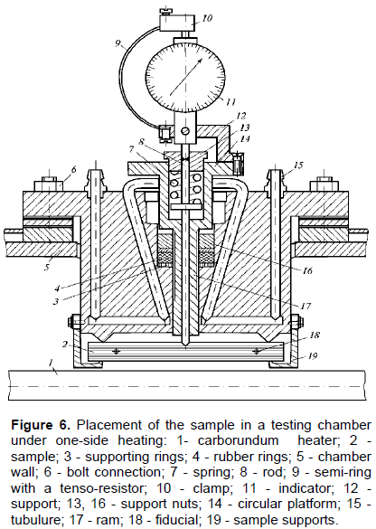
In the layer at a distance of 3 mm from the heated surface of the sample, fiducials 18 was set (Figure 6); it was registered in the heating process automatically. Heating rate in the studied layer was 25, 50, and 100°C/min (Gracheva, 2016).
Temperature distributions in the sample were defined using platinum-platinum/rhodium thermocouples; it was set on a heated surface (Tp1), in the middle of the sample at a depth of the tested layer (Tp2), and on the opposite from the heating side of the sample (Tp3). Thermocouple 2 was the leading one in testing, and according to its readings, the heating program was set.
Results of the samples from fiberglass CCTF in a one-sided heating at different rates are as shown in Figure 7.
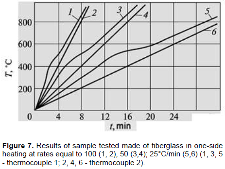
Temperature in the studied layer of the sample was set as a linear function of time: T2(t) = T0 + Vht, where T0 = 20°C - initial temperature; t - time of thermal action. Temperature on the cooled side of the sample in testing was changed insignificantly (25-28°C) for all heating rates and is not shown in the figure.
Temperature field over the sample thickness at different time was defined according to the accepted heating scheme; it corresponded to conditions of regular regime and the test results obtained. Experiment scheme in defining temperature field gives an opportunity to consider a sample as an infinite plate heated from one side on linear dependence with sustaining temperature constant on the other side. Analysis of temperature curves (Figure 7) allows one to assume that temperature fields can be described by a polynomial of the second degree (Tret'yachenko et al., 1981):
T = Ay2 + By + D
where y – distance to the heated surface. Constants A, B, D are defined from boundary conditions:
Ty=0 = T1, Ty=1 = T2, Ty=0 = T3,
where T1, T2, T3 – temperatures obtained experimentally. Results of computation of temperature fields over the sample thickness at heating rates of 25 and 100°C/min showed that (Gracheva, 2005) decrease of the heating rate gets closer to the distribution of temperatures over the cross-section of the sample to a linear one.
Change of mechanical and thermo-physical properties of fiberglass under the conditions of increasing one-sided thermal action is inherently connected to the state of structure of the material in the heating process. Heat supplied in the initial moment to the heated surface of the sample is absorbed by a material and is brought to the lower lying layers with a small rate due to the low thermal conductivity of the fiberglass. As the temperature increases up to some limit (300 - 400°C) in the surface layers, thermal decomposition of the binder starts depending not only on temperature of testing but also on duration of thermal action. With an increased temperature and time of heat supply, the zone of thermal destruction permanently shifts from a heated material inside, and the remaining thermal coke; it is indicated by decreased rate of temperature increase T1 after the start of pyrolysis (Figure 7).
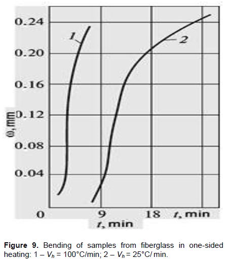
Results of temperature deformation of fixed samples in one-sided thermal action are shown in Figure 8. In the experiment, the sample bending w was excluded by sample loading from the side opposite to heating. The bend w in one-sided heating in a free, non-fixed state was recorded separately (Figure 9) (Gracheva, 2006 and 2016).
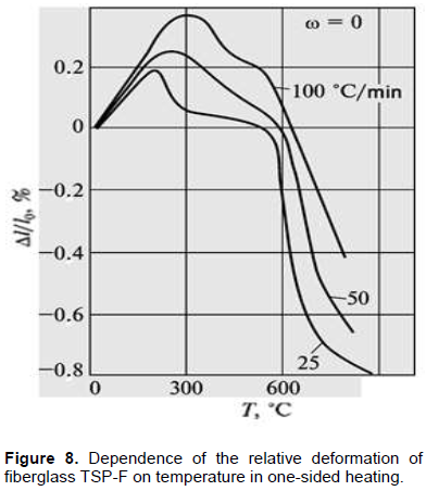
On the given curves it is seen that in one-sided heating, the curves of thermal deformation sharply shift to the zone of large values of deformations and temperatures, if they are compared with analogous curves obtained for the same material under conditions of a homogeneous temperature field. For comparison, Table 2 shows some characteristic points of curves of thermal deformation of samples from fiberglass in a homogeneous and in one-sided heating.
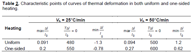
The difference of values of similar points under non-equal types of thermal action at a heating rate of 50°C/min is higher than that at the heating rate of 25°C/min. Thus, if the largest expansion for Vh = 25°C/min is higher than that in one-sided heating as much as 2.2 times, then at Vh =50°C/min it is as high as almost 3 times. Also, the values of shrinkages obtained at temperature 800°C and heating rate of 25°C/min in one-sided heating are lower than the corresponding values in a homogeneous heating 1.67 times; while at 50°C/min, it is 1.93. For the temperatures used to cross the curves of thermal deformation, the x-axis obtained in one-sided heating also shifted in the area of large values for Vh = 25°C/min - on 15%; for Vh = 50°C/min - on 20%.
Physically it is clear that the conditions of the experiment are such that on the opposite, cooled side of the sample there is constant room temperature. Even though in the surface layers of the material, there is high temperature shrinkage as a result of thermal destruction, the medium layers of the material under given heating rates and corresponding temperature fields are in the zone of thermal expansion. This defines, in general, the integral characteristic of thermal deformation of the material.
Thus, dependencies of thermal deformation defined in one-sided heating of mechanically loaded fiberglass samples based on phenol-phormaldehyde, witness a substantial decrease in the level of shrinkage in the material simultaneously with increase in the zone of expansion compared to the curves obtained under conditions of homogeneous heating at the sametemperat ures.
A thermal stressed state
Computation of a stressed-deformed state was performed for rectangular samples from a reinforced plastic, operating under conditions of a force load and thermal load. Having characteristics of thermal deformation and temperature distribution in sample cross-section, one can evaluate thermal stresses that cause sample bend in one-sided heating. The problem was solved considering an elastic equilibrium of a homogenous orthotropic body (Becker, 2014; Tanigawa et al., 1995).
To determine thermal stresses in the loaded (straightened) sample, we use the expression,
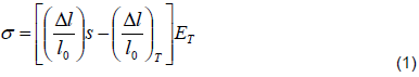
where (Δl/l0)s - relative elongation of the straightened sample; (Δl/l0)T - relative elongation of the homogeneously heated sample (dilatometric values); ET - Young modulus at a given temperature. A stressed state of the bent (free) sample was obtained by putting in a field of stresses (Equation 1) of the bend stress with an opposite sign:
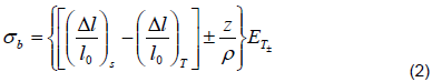
where r - radius of neutral plane of the sample of the thickness d with coordinates x, y, z: y£ z £d - y1 (Grigirenko et al., 2018).
Distribution of stresses in the sample heated at the rate of 100°C/min and a given depth is shown in Figure 10. In computation, the dependence (Δl/l0)T on the heating rate over the material thickness was taken into account. Numerals I and II designate curves of distribution of stresses in the loaded and free samples were correspondingly heated at the rate of 25°C/min for 8 min when the heat started, that is, the peak moment of the values of thermal expansion. Increase in the heating rate for both free and loaded sample in the range of linear dependence of the coefficient of thermal deformation on temperature (up to T = 300°C) causes increase in the stress gradients. Temperature increase above 300°C for fiberglass leads to an increase in the plasticity of the material that achieves its maximum at the temperatures when transition of curves of thermal deformations (Figure 8) takes place, from positive to negative (Gracheva, 2019).
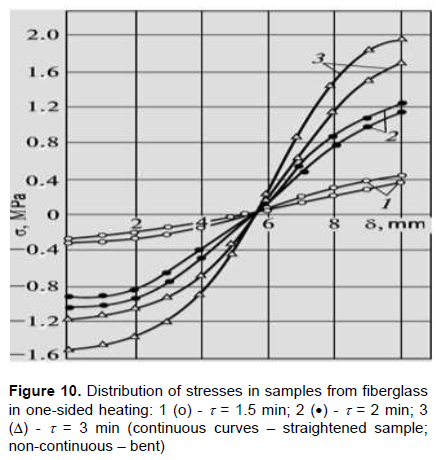
Thus, due to the rheological properties of the binder, the material, in a general case, is unloaded and stresses will be not that high, as the problem is solved in elastic sense.
At the temperature range of non-linear behavior of aT,, stresses appear just to prevent a free bending of the sample, that is, for a bent sample, the gradient of stresses is absent (Ds = 0).
Figure 11 shows an integral TD of weakly-conical shell, made of fiberglass fabric CCTF. It was obtained in a test of high-temperature gas flow at a high density (q ~ 500 kcal/m2s; Tmax ~ 2500°C) under modelling conditions of a re-entry spacecraft in dense atmospheric layers (Malkin, 1991).
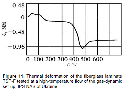
At the temperature of deformation of fiberglass obtained in one-sided heating set-up on DTM, there was thermal expansion of the outer layers of large-size models of thermal shield structures (L = 340 mm, D = 240 mm) under testing conditions close to natural ones (Figure 2) (Gracheva, 2019).
CONCLUSION
An experimental and analytical study of thermal deformation of thermal shield material under one-sided heating and real modeling conditions is implemented; comparison is made with dilatometry data obtained in a homogeneous temperature field.
A research method used to study the kinetics of thermal deformation of composite materials under one- sided heating is described.
It is demonstrated that under one-sided heating, the absolute values obtained from samples deformed by thermal heat made of fiberglass based on phenol-phormaldehyde matrix increase more than twice compared to the values obtained for the same thicknesses at the same temperature-time interval.
An increase in the heating rate under one-sided heating, and uniform heating shifts deformation curves to the region of larger values and temperatures. This is due to the decrease in the time of thermal action necessary for phase transitions to occur in the material.
One-sided heating causes an increase in the stress level at high heating rates (100°C/min), of up to 14-15% in the stretching zone, up to 30% in the compression zone, and almost three-fold increase in the level of stresses of both signs at low heating rates (25°C/min).
There is a correspondence between the values of thermal deformation obtained under conditions of one-sided heating and an integral thermal deformation of large-size models of a thermal shield tested under real modeling conditions.
CONFLICT OF INTERESTS
The author has not declared any conflict of interests.
REFERENCES
|
Becker W (2014). Available theories for an analysis of stresses and assessment of strength of laminate structures. MCM 5:759-779. |
|
|
Dimitrienko YE (1997). Mechanics of composite materials under high temperatures, Moscow, Mashinostroenie. |
|
|
Dreiper NP, Smith G (2016). Applied Regression Analysis, 3-rd Ed. |
|
|
Dzenis YA, Ponomaryov VM (1989). Thermal expansion of a polymer composite with an aggregating dispersive filler. MKM 1:70-77. |
|
|
Gracheva L (2004). The influence of thermal stresses on the strength of carbon materials at high temperatures, Materials and Coatings for Extreme Environments Performance: Investigations, Applications, Ecologically Safe, Technologies for their Production and Utilization: Proceeding. 3-th Int. Conference. 13-17 Sept.:243-244. |
|
|
Gracheva L (2019). Predicting performance of thermal shield of a spacecraft in high-temperature gas flow, Journal of Mechanical Engineering Research 2(1):25-35. |
|
|
Gracheva L, Kharchenko V (2006). Deformation of thermal protection coatings from glass-fiber reinforced plastic under conditions simulating a spacecraft reentry, Proc. 1-st Int. Conf. on Atmospheric Reentry Systems of Missions and Vehicles (ARA Days), Arcachon, France pp. 77-78. |
|
|
Gracheva LI (2005). Thermal stresses in composite materials at the manufacturing stage, Proc. of the Congress on Thermal Stresses 05, Vienna, Austria, 26 May-3 June, 2005, Vienna pp. 63-766. |
|
|
Gracheva LI (2006). Thermal deformation and operating efficiency of thermal shield materials, Kiev, Naukova Dumka. |
|
|
Gracheva LI (2016). Optical-geometrical methods of investigation on the heat deformations of non-metallic composite destructive materials in the temperature range of 20 to 1200 ºC, Proc. 4-th International Conference on Advanced Materials Science and Technology (AMST 2016), Oct 30-31, 2016, Bangkok, Thailand pp. 283-286. |
|
|
Grigirenko YM, Grigorenko AY, Zakhariichenko LI (2018). Analysis of the Effect of Geometrical Parameters of Elliptic Cylindrical Shells of a Variable Thickness on Their Stress-Strain State. Applied Mechanics 54(2):42-50. |
|
|
Khobragade NL, Deshmukh KC (2005). Thermal deformation in a thin circular plate due to a partially distributed heat supply, Sadhana, Academy Proceedings in Engineering Sciences 30(4):555-563 |
|
|
Lehnitsky SG (1977). Theory of Elasticity of an Anisotropic Body, Moscow, Nauka. |
|
|
Malkin AJ, Kulichikhin S (1991). Advances in Polymer Science 96:69. |
|
|
Marasin BV, Gracheva L, Ruban V (1991). Patent 1656428 (USSR). Setup for dilatometric testing under high temperatures. Bulletine 22. |
|
|
Perepelkin KE (1992). Fibers and fiber materials for reinforcing composites with extreme characteristics. MKM 3:291-306. |
|
|
Polezhaev Ju, Jurevich F (1976). Thermal Protection, edited by A.V. Lykov, Energia P 391. |
|
|
Tadmor Z, Gogos C (2006). Principles of Polymer Processing, Second Edition. John Wiley & Sons, Inc: 668 p |
|
|
Tanigawa Y, Takahara T, Kawamura R, Nagayama K (1995). Analysis of Thermal Stress and Deformation due to Nonuniform Heat Supply in an Angle-Ply Laminated Rectangular Plate. Transactions of the Japan Society of Mechanical Engineers Series A 61(584):784-790. |
|
|
Tret'yachenko G, Gracheva L, Vengzhen V (1981). Analysis of the state of stress and strain of the elements of model degradable glass-reinforced textolite heat shields subjected to one-sided heating. Mechanics of Composite Materials 16(5):568-572. |
|
|
Tretyachenko GN, Gracheva L (1986). Problems of dilatometry for destructing composite materials. Izmeritelnaya Technica 10:40-42. |
|
|
Voloshchenko AP, Kuzema YA, Aleksyuk MM, Grishko VG, Fot NA (1980). Testing methods for studying the strength of materials. Strength of Materials 12(10):1332-1340. |
|
Copyright © 2024 Author(s) retain the copyright of this article.
This article is published under the terms of the Creative Commons Attribution License 4.0


