ABSTRACT
In the presented study, by applying analytical methods and using experimental data, equations are achieved to predict the fatigue life of unidirectional carbon fiber/epoxy composite (UCFEC) that is applied in aerospace structures. The experimental data used to obtain these equations are achieved by low earth orbit (LEO) environment simulation experiment and other experiments. By employing convex curves analytical method, some equations to predict the fatigue life of unidirectional carbon fiber/epoxy composite in LEO are achieved. Then, by inspiration of convex curves method, steady-linear method to predict the fatigue life of unidirectional carbon fiber/epoxy composite on Mars is proposed. Furthermore, the results of convex curves method have proved that the main factor causing fracture of UCFEC in vacuum thermal cycles is the degradation of inter laminar shear strength between the carbon fiber and epoxy. Finally, the results obtained by these methods are compared with the results from other experiments of composite materials. The comparison showed that the results of this study seem acceptable.
Key words: Fatigue life prediction, unidirectional carbon fiber, composite, earth orbit, Mars.
Mars
Planet Mars has been the centre of attention for many scientists and people due to its reddish colour and the possibility of existing life on this planet (Pasachoff, 1993). Mars is a small planet, 6800 km across, which is only about half the diameter and one-eighth the volume of Earth or Venus, although somewhat larger than Mercury. Mars’s atmosphere is thin-at the surface with its pressure only 1% of the surface pressure of Earth’s atmosphere; however, it might be sufficient for certain kinds of life. It turns out to be 24 h 37 min 22.6 s from one Martian noontime to the next, so a day on Mars lasts nearly the same length of time as a day on Earth. Mars revolves around the sun in 23 Earth months. Surface temperatures measured from the landers ranged from a low of 150K at the northern site of lander 1 to over 300K at lander 2. Temperature varied each day by 35 to 50°C (Pasachoff, 1993).
Human missions to Mars have been studied by many authors (Salotti, 2011, 2012). Likelihood of vehicular mission-success-and-safety is investigated by Suhir (2012). The Mars500 mission was a 520-day long simulation of a round trip to Mars. After going through an intense selection process, 6 individuals from various countries lived and worked for several months in a pressurized facility in Moscow, Russia, mimicking as close as possible the conditions of real space flight. The simulation concluded in November 2011 when the crew came out of the facility in seemingly good health and mood (Diego and Charles, 2014). Conceptual study of Mars Aero-flyby Sample Collection (MASC) is conducted as part of the next Mars exploration mission currently entertained in Japan Aerospace Exploration Agency (Fujita et al., 2014). Some major risks-of-failure issues for the future manned missions to Mars are discussed, with an objective to address criteria for making such missions possible, successful, safe and cost-effective (Salotti and Suhir, 2014).
Water on Mars
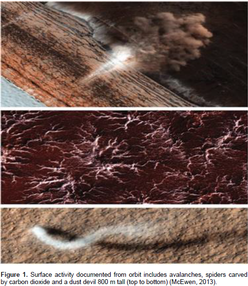
It seems that water is essential for existing life for every creature on Earth due to sustaining metabolism and cellular structure stability (Des Marias, 2010). A student in the laboratory discovered a perplexing feature of Mars’s surface that had never been seen before- streaks across the surface, flowing downhill, that grow slowly and change with the seasons in ways that suggest they are flows of liquid water (Figure 1; McEwen, 2013). Photographs from the Phoenix mission showed what looked like water droplets on the legs of the robotic lander (McEwen, 2013). Frost deposits observed occasionally only at the Viking-2 lander site (48°N, 226°W) on Mars (Mohlmann and Thomsen, 2011).
A one-way human mission to Mars
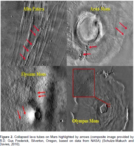
It sounds like Mars is the most similar planet to Earth due to its moderate surface gravity, atmosphere, and existing water and carbon dioxide. Therefore, it may be considered as a second home of human in solar system. After Venus, Mars is the nearest planet to Earth and trip to Mars takes about six months according to recent space technology (Schulze-Makuch and Davies, 2010).The astronauts would go to Mars with the intention of staying for the rest of their lives, as trailblazers of a permanent human Mars colony. They would be resupplied periodically from Earth, and eventually develop some home grown industry such as food production and mineral/chemical processing. Their role would be to establish a base camp (Figure 2) to which more colonists would eventually be sent, and to carry out important scientific and technological projects in the interim (Schulze-Makuch and Davies, 2010).
Over time, the human contingent on Mars would slowly increase with follow-up missions. Several cave-centered biospheres would be created, each being in constant communication with other cave-centered biospheres to share experiences on which approaches are working best. At some later time, probably several decades after the first human mission, the colony’s population might have expanded to about 150 individuals, which would constitute a viable gene pool to allow the possibility of a successful long-term reproduction program. New arrivees and possibly the use of genetic engineering would further enhance genetic variety and contribute to the health and longevity of the colonists (Schulze-Makuch and Davies, 2010).

Carbon fiber/epoxy composite
It appears that since 1930s polymers have been used in different applications like clothing, carpets, ropes, and reinforcing due to its versatile forms like films, fibers, sheets, and coatings (Song et al., 2013). Composites are materials widely used lately in the aeronautical industry to manufacture several parts as flaps, aileron, landing-gear doors and others. Polymer matrix composite materials constituted by continuous carbon fibers embedded in a thermosetting epoxy resin were first developed to satisfy high standards required in aircraft design. Compared to metals, the epoxy/carbon composites offer similar or better mechanical properties by mixing in these two distinct phases, fibers and resin, and adopting different fiber configurations (Voicu, 2012). As a contribution to this field of study, development and mechanical properties of carbon fibre reinforced EP/VE hybrid composite systems is performed by Meszaros and Turcsan (2014).
Fatigue, damage, and fracture
In order to accurately determine the fatigue life of composites, some factors are required to be considered. These factors may include; stress amplitude, mean stress, and frequency and waveform of stress cycling during service (Hertzberg, 1989; Sendeckyj, 1990; Harris, 2003).In application of theories for fatigue, damage, and fracture, determination of stress intensity factors in half-plane containing several moving cracks is investigated by Malekzadeh Fard et al. (2013). Basic solutions of multiple parallel symmetric mode-Ó€Ó€Ó€ cracks in functionally graded piezoelectric/piezomagnetic material plane is proposed by Pan et al. (2013), while nonlinear progressive damage model for composite laminates used for low-velocity impact is evaluated by Guo et al. (2013). In addition, recent technique for thermal-fatigue simulation of heat-resistant steels is provided by Biro and Csizmadia (2012). Furthermore, in the area of obtaining the analytical evaluation methods of materials’ properties, a few works are submitted by Anvari (2014, 2016, 2017; Adibnazari and Anvari, 2017).
Advanced carbon fiber-reinforced composite laminates have been widely used in satellite structures, where the advantages of these materials- their high specific stiffness, near-zero coefficients of thermal expansion (CTE) and dimensional stabilities make them uniquely suited for applications in a low-specific-weight environment. However, since the beginning of composite structure applications, there has been a strong need to quantify the environmental effects on the composite materials based on the coupon-level laminate test data. Recent studies have shown that the environmental conditions that are the most representative of space and that tend to degrade the properties of composite laminates involve vacuum, thermal cycling atomic oxygen (AO) and micrometeoroid particles. In this respect, there is significant interest in the construction of an experimental database to capture the collective understanding of the degradation mechanisms of composite laminate in in-service environments. It is necessary to be able to predict the long-term durability of composite laminates with engineering accuracy to use these materials with confidence in critical load-bearing structures (Park et al., 2012).
One of environmental effects of space known to induce environmental degradation is thermal cycling because a satellite in low earth orbit (LEO, between 100 and 1500 km above the earth’s surface) passes in and out of the earth’s shadow. The exterior surface is exposed to long- term periodic sharp temperature changes as a result. This type of non-mechanical fatigue is of significant concern for the design of composite laminates because of the strong anisotropy of the thermoelastic characteristics of the long-fiber unidirectional plies. Considering the importance of the vacuum thermal cycling, several studies have been conducted in this area. Gao et al. (2005); Shin et al (2000); Funk and Sykes (1989) in particular have focused on the fundamental understanding of cumulative damage development due to cyclic exposure. However, such research should be expanded. The limited number of thermal cycles (350 cycles or less) used in their studies should be expanded to draw a definite conclusion, and studying the effects of thermal cycling on more representative space-grade materials for LEO application combined in series with mechanical assessments is required to assess the long-term durability issues of these materials (Park et al., 2012).
In the presented research, the effect of thermal cyclic exposures on unidirectional carbon fiber/epoxy composite (UCFEC) in Mars environment is investigated. Carbon fiber/epoxy composite is a candidate material applied in aerospace structures which might be deployed in LEO or land on Mars. The cumulative degradation effects on modulus and mechanical strength for UCFEC due to thermal cyclic exposures is considered and calibrated to predict the fatigue life in Mars environment. These data are obtained from the simulation of LEO environment in laboratory (Park et al., 2012) and another experiment (Nakamura et al., 2007). In this study, by applying analytical methods and using the experimental data, equations and methods to obtain the fatigue life of UCFEC in LEO and Mars environments are achieved.
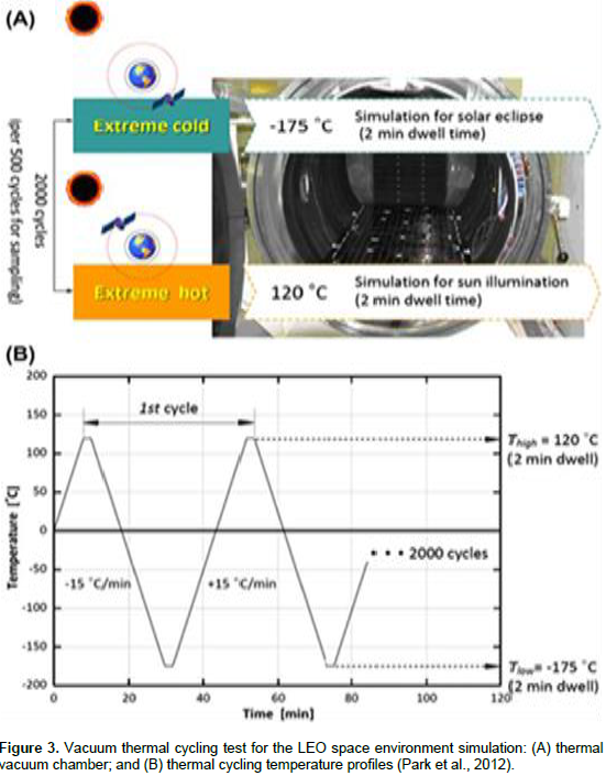
The thermal cycling tests were conducted using a thermal vacuum chamber (Hanchang Eng, South Korea), as shown in Figure 3A (Park et al., 2012). The experiment was performed in an environmental chamber with a proportional integral derivative (PID) programmable temperature controller. Test temperature range should be as large and practicable to meet environmental stress screening (ESS) purposes based on the guideline in MIL–STD-810F and MIL-STD1540C. It is generally required to reveal potential flaws in material exposed to more extreme temperature change condition. In this study, extreme temperature conditions (120 to -175°C) encompass an environmental severity over that expected during service life based on the previous studies. Common to each of the thermal cycling profiles, low temperature (Tlow = -175 ± 5°C) simulates the solar eclipse condition and cycle-specific high temperature (Thigh = 120 ± 5°C) corresponds to the sun illumination for each 2 min duration time, as shown in Figure 3B (Park et al., 2012). Following this profile, one cycle was designed as the sequence from 120 to -175°C and back to 120°C so that the total duration of each cycle was approximately 43 min. A vacuum pressure of 1.3-3 Pa was employed throughout the thermal cycling test (Park et al., 2012).

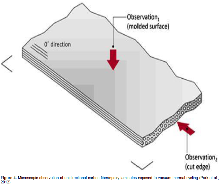
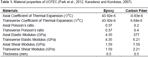
The extent of degradation was determined experimentally by exposing the test panels to vacuum thermal cycling. The experiments were repeated for 500 cycles (358 h), 1000 cycles (716 h), 1500 c ycles (1074 h) and 2000 cycles (1432 h). Following the thermal cycling exposure, all partly-or fully-aged test panels were cut into the desired dimensions using a water-cooled diamond saw and subsequently dried in a vacuum oven at 60°C for 24 h to remove moisture after the cutting operation. Series of physical and mechanical tests were then performed in the standard laboratory atmosphere of 23 ± 2°C and 50 ± 5% rh on the baseline (unaged) and environmentally conditioned test samples (Park et al., 2012). In Figure 4 (Park et al., 2012), the sample of UCFEC used in simulation experiment in LEO environment is shown. In the following parts of this study, by the existing assumption in LEO environment and material properties of UCFEC, crack density growth rate can be obtained. In Table 1, the material properties of UCFEC are indicated.

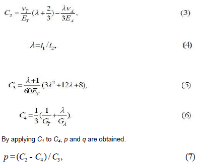
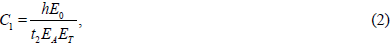
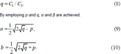
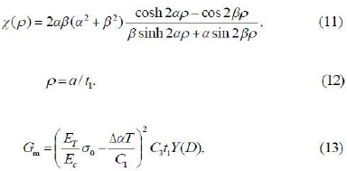
In this part of the research, equations that are used to obtain the relation for estimating the fatigue life of UCFEC in LEO environment simulation experiment and Mars environment are introduced. In the Equations 2 to 17 (Liu and Nairn, 1990), EA and ET are the axial and transverse moduli of the carbon fiber, Ec is the modulus of the epoxy laminate, Ts is the specimen temperature, while T0 is the temperature when the laminate is uncracked and at the stress free temperature. E0 is

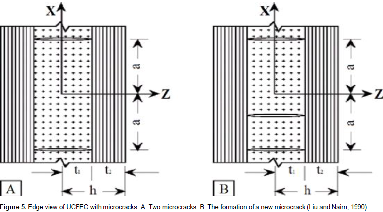
∆α = αT − αA (the difference between the transverse and longitudinal thermal expansion coefficients of carbon fiber). T = Ts − T0. Finally, p, q, and the constants C1 to C4 are functions of the mechanical properties and thicknesses of the plies: t1 is half thickness of epoxy, t2 is the thickness of carbon fiber, and h = t1 + t2 as shown in Figure 5 (Liu and Nairn, 1990).
GA, GT, νA, and νT, are the axial and transverse shear moduli and Poisson’s ratio, respectively, while Gc is epoxy shear modulus. Note that the above solution is specific for 4q/p2 > 1.


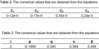
In Tables 2 and 3, the numerical values obtained by the above equations are indicated.
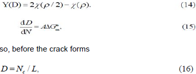
In Figure 6, B = 2h is the total thickness, W is the sample width (y-direction dimension), and L is the sample length (x-direction dimension). In this research, as shown in Figure 6, B = 1 mm, W = 5 mm, and L = 25 mm. With the present assumption, the numerical values in the paper, and Table 1, the numerical values in Table 2 are obtained.
where Gm is energy release rate and Y(D) is a calibration function that depends on the crack density, D. The calibration function is therefore (Anvari, 2017)


and after the crack forms
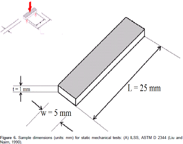
It is proposed that fatigue data be analyzed using a modified Paris-law approach in which the rate of change in microcrack density is given by Equation 15, where A and n are two power-law fitting parameters. The conventional Paris-law approach relates the rate of change in crack length to the range in the applied stress intensity factor-∆K. In the microcracking fracture experiment, the stress intensity factor approach is not possible and therefore ∆G is substituted for ∆K (Liu and Nairn, 1990). In this research, the sample did not withstand longitudinal tensile stress, hence Ϭ0 is equal to zero. As a result, Equation 13 changes into Equation 18.

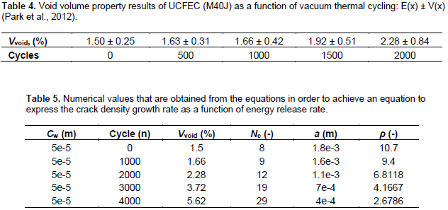
By substituting the necessary numerical values achieved by this experiment in Equation 18, Gm numerical value (energy release rate) is obtained. It appears from Equation 18 that as subtraction between T0 and Ts increases, the numerical value of Gm increases. As mentioned before, T0 = 23°C; therefore, if the numerical value of Ts = -175°C, the numerical value of Gm can be maximum. For measuring the distance between the cracks, 2a, such that the width of each crack is assumed 5e-5 m, Table 4 (Park et al., 2012) is used. In the present research, the volume percent of void (Vvoid) in sample is assumed to be equal to longitudinal percent of void.
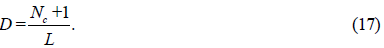
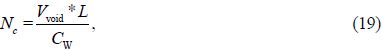
By using the numerical values in Table 4 and present assumptions, the numerical values in Table 5 are achieved. The numbers of cracks, Nc, are obtained from Equation 19 such that Vvoid is the void volume percent of sample, L = 25 mm, the sample length, and Cw is the crack width. It is important to notice that the LEO simulation experiment is performed for 2000 vacuum thermal cycles, and the approach used to obtain the void volume percent in sample for 3000 and 4000 cycles is explained in the following.

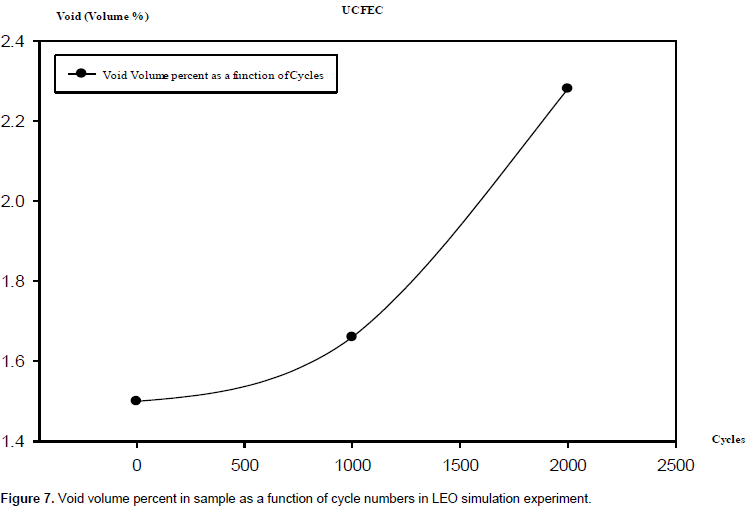
In Table 4, the void volume percent in (M40J) UCFEC for the cycles 0, 500, 1000, 1500 and 2000 in LEO simulation experiment are shown. By using these data from Table 4, an equation to obtain the void volume percent in LEO simulation experiment in any cycle is possible. This equation indicates the void volume percent in UCFEC as a function of cycle numbers. By using this equation, and by applying partial derivative, obtaining the numerical value of void volume percent growth rate is possible. In this research, the void volume percent growth rate is assumed to be equal to crack density growth rate because it seems that the only void volume growth rate is due to crack density growth rate. It is noticeably the function of crack density growth rate obtained in this study (Equation 26) that indicates approximately the maximum of possible crack density growth rate.
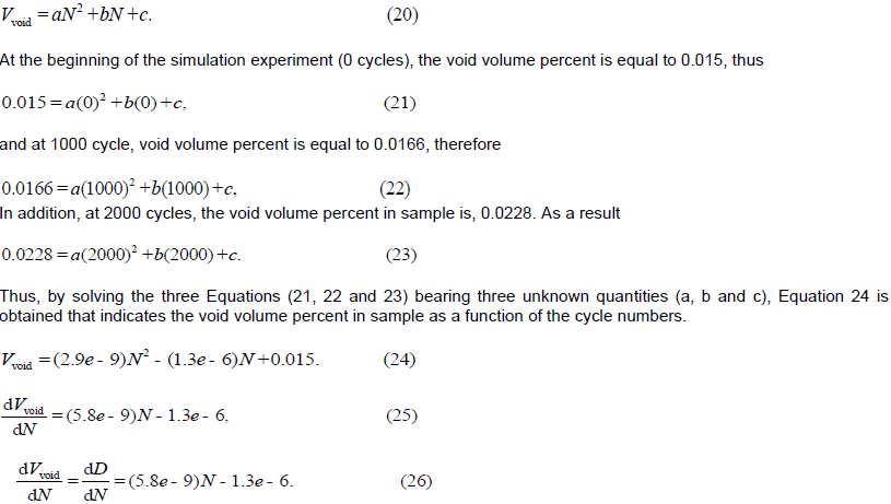
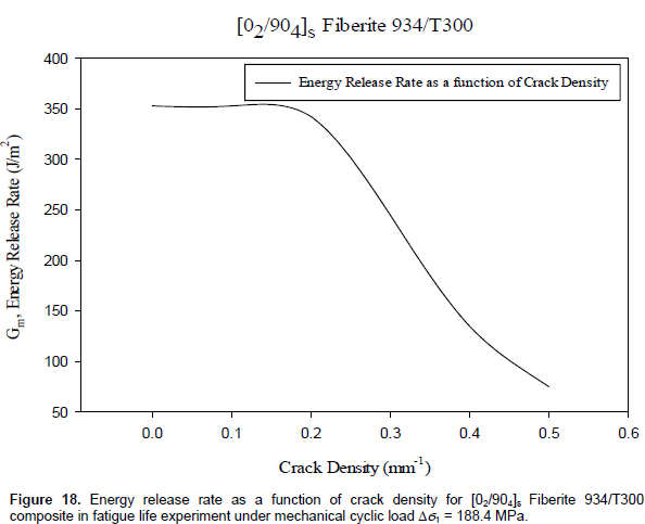
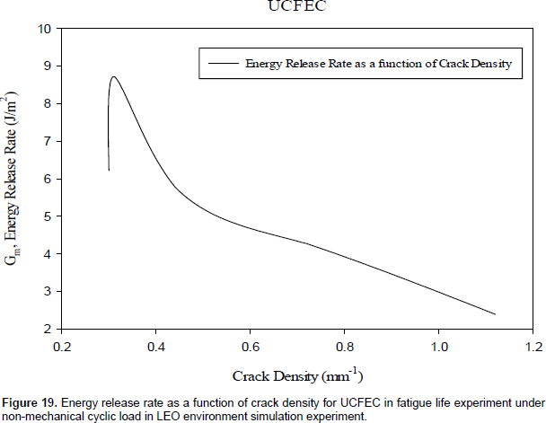
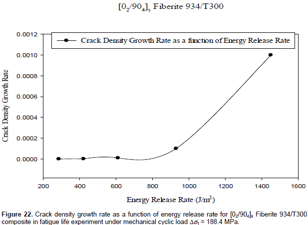
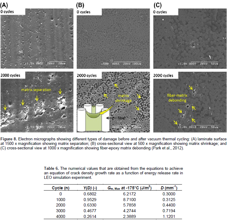
In Figure 7, void volume as a function of cycle numbers in UCFEC in LEO simulation experiment is shown. By applying the Equation 24 and substituting 3000 and 4000 as the number of cycles, the numerical values 0.0372 and 0.0562 for void volume percent are obtained. By employing partial derivative for Equation 24, void volume percent growth rate or crack density growth rate in LEO environment simulation experiment for UCFEC is obtained and indicated in Equations 25 and 26. In Figure 8 (Park et al., 2012), the cumulative degradation of sample due to vacuum thermal cycles in LEO environment simulation experiment is shown. Obviously, regarding Table 6 crack density numerical values of 0.3 to 0.3125 mm-1, ∆G is increased; hence, the calibration of microcrack propagation is simple. Crack density as a function of cycle numbers is induced for different âˆ†Ï numerical values due to temperature change. In crack density numerical values of 0.3 to 0.3125 mm-1, Gm is increasing (6.2172 to 8.7100 J/m2). In this region, by obtaining the curve slope, the crack density growth rate and a relation between crack density growth rate and energy release rate are obtained. Subsequently, in this research, the results obtained from this relation are compared with the results from another fatigue life experiment for [02/904]s Fiberite 934/T300 composite under the mechanical cyclic load ∆Ï1 = 188.4 MPa.

Equation 27 is related to [02/904]s Fiberite 934/T300 composite under cyclic load, while Equation 28 is related to UCFEC in vacuum thermal cycles at LEO environment simulation experiment.
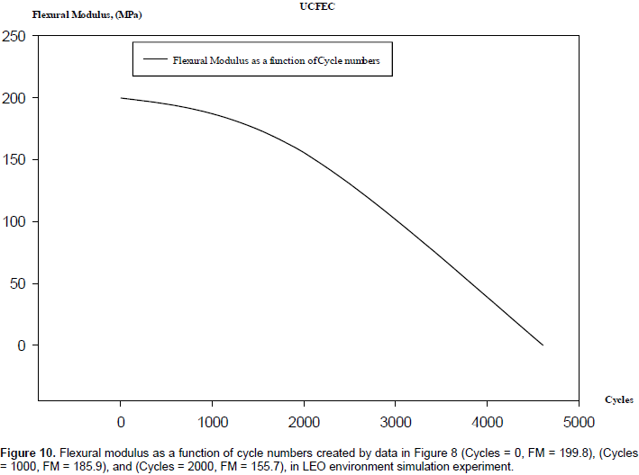
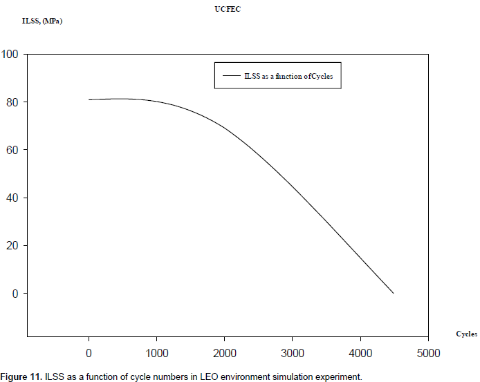
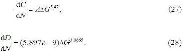
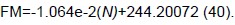
In this part of the study, a method for fatigue life prediction of UCFEC in LEO environment simulation experiment, by applying an analytical approach and using the experimental results, is achieved. The experimental results used to develop the convex curves method are obtained from vacuum thermal cyclic exposures (Park et al., 2012). In this method, by considering the data from experimental results and finding the points that develop convex curves, numbers of functions to predict the fatigue life of UCFEC are obtained.Figure 9 (Park et al., 2012) indicates the results of LEO environment simulation experiment after going through 0, 500, 1000, 1500, and 2000 of vacuum thermal cycles. The functions obtained from these results are useful in predicting the fatigue life of UCFEC in satellite or space application, since UCFEC can be used in the structures of satellites and space crafts. In Figure 9, there are many data for inter laminar shear strength (ILSS), flexural strength (FS), flexural modulus (FM), etc. In order to use the convex curves approach, for example in ILSS, Figure for M40J, using the three points (Cycles = 0, ILSS = 80.9), (Cycles = 1500, ILSS = 75.7), and (Cycles = 2000, ILSS = 69.1), and by solving three equations, three unknown quantities, like the method used to develop Equation 24, a convex curve is developed.

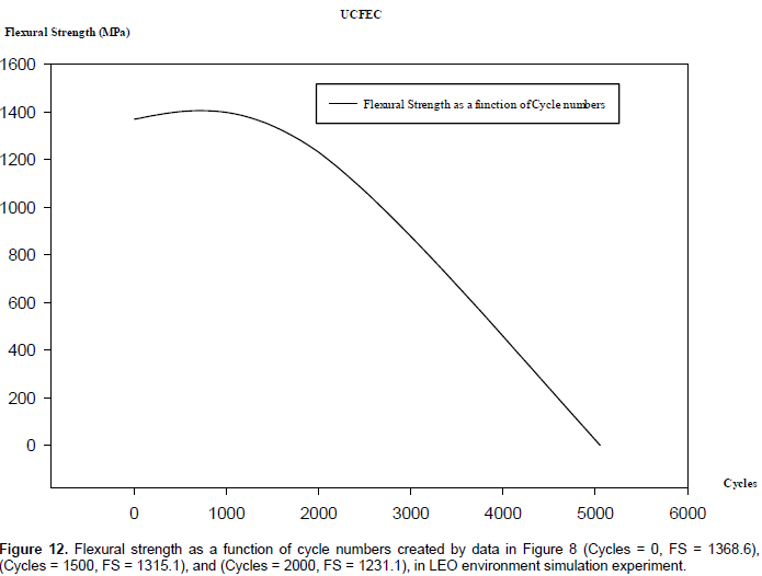
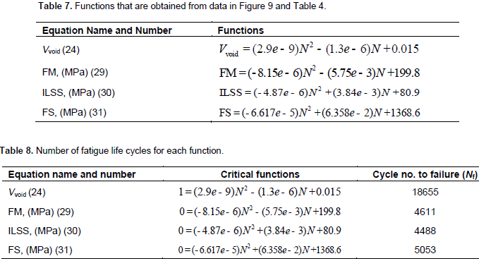
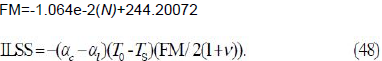
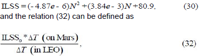
This convex curve in a determined coordinate can intersect the cycle axis at zero ILSS. It means that, the numerical value of the cycle number achieved by this method can indicate the fatigue life of the UCFEC in LEO environment. This process to find more convex curves to predict the fatigue life is repeated. For the material M40J which is a UCFEC, only three convex curves: ILSS, flexural strength (FS), and flexural modulus (FM), from the data of the Figure 9 (Park et al., 2012) is obtained. The other data for M40J, such as longitudinal tensile strength, longitudinal compressive strength, longitudinal tensile modulus, and longitudinal compressive modulus can develop concave curves which might never intersect the cycle axis. Therefore, it seems, predicting the cycle number to failure by employing the concave curves is impossible.The functions of convex curves obtained by this analytical method are indicated and shown in Table 7 and Figures 10 to 12, respectively. By solving Equation 29 while it equals to zero, a cycle number to FM failure is obtained; by solving the Equation 30 while it is equal to zero, a cycle number to ILSS failure is achieved; and by solving the Equation 31 while it equals to zero, a cycle number to FS failure is obtained. The cycle numbers for each failure are indicated in Table 8. It appears that the most likely fracture state is that of ILSS because the cycle number to failure for this state is the minimum cycle number.
Convex curves method analysis
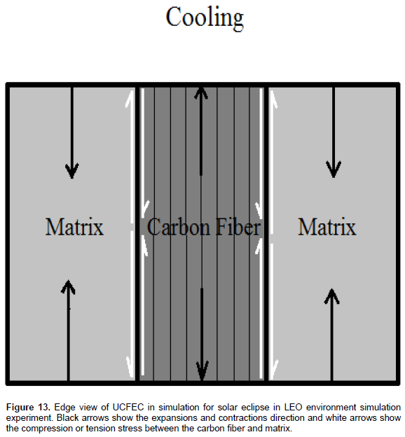
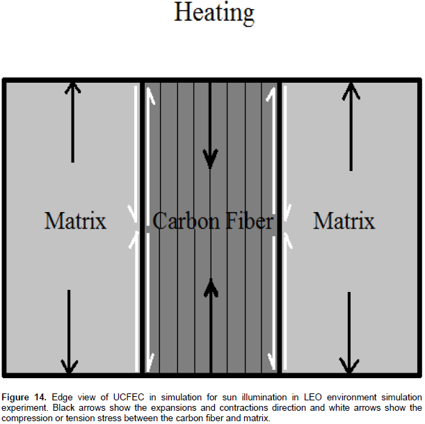
Obviously, from Table 8, the minimum cycle numbers of fatigue life is due to ILSS. It means that, the cause of failure in UCFEC can be due to degradation in ILSS. In order to investigate the fracture process, it is reasonable to conclude that, as it seems that the result of degradation in ILSS is the main cause of fracture, it appears that the matrix debonding of UCFEC is the main cause of fracture. Thus, based on the convex curves method analysis, debonding between carbon fibers and epoxy is the most likely state of fracture. Therefore, it appears it is right to conclude that, because the number of cycle to failure obtained due to degradation of flexural modulus is greater than the number of cycle to failure due to degradation of ILSS, as a result, it is a second probable mode of fracture. Furthermore, it is concluded that, third probable state of fracture is due to the flexural strength degradation of UCFEC because the cycle number to failure for this state is greater than the cycle number to failure due to degradation of flexural modulus. In Figures 13 and 14, the fracture phenomenon due to the degradation of UCFEC’s ILSS exposed to vacuum thermal cycles is shown.


Fracture process analysis
As proven previously, it seems that the most likely state of fracture in UCFEC in LEO simulation experiment is the fracture due to the degradation of ILSS. Vacuum thermal cyclic fatigue, which is a non-mechanical fatigue is the main cause of failure in LEO environment. Hence, to analyze the fracture process, a thermal analysis is necessary. While the UCFEC is exposed to sun illumination in LEO, temperature raises from 23 to 120°C. In UCFEC, due to longitudinal coefficient of thermal expansion for carbon fiber and epoxy which are negative and positive respectively, carbon fiber tends to contract in longitudinal axis; however, epoxy tends to expand in longitudinal axis. In this state, carbon fiber withstands tensile force while epoxy withstands compressive force. Whereas the UCFEC is exposed to solar eclipse in LEO, temperature decreases from 23 to -175°C. In this condition, the epoxy withstands tensile force while the carbon fiber withstands compressive force. Because the carbon fiber and epoxy are stuck together, due to this reverse behavior of carbon fiber and epoxy in longitudinal direction, cracks are induced especially in the interface-bonding surface between fiber and matrix. By continuing the thermal cycles, the cracks are propagated and by the propagation of cracks, ultimately, the fracture is occurred.
In this part of the study, a method to predict the fatigue life of UCFEC in Mars environment is proposed. In order to achieve this method, the results of convex curves method are employed. As proven by convex curves method, the main cause of fracture in UCFEC in low earth orbit exposed to vacuum thermal fatigue is due to the degradation of ILSS between carbon fiber and epoxy. Because the only non-mechanical cyclic load that exists in LEO and Mars environment is the thermal cyclic load, the results of convex curves method can be applied to predict the fatigue life on Mars. Based on this assumption, temperature variation in Mars is the main thermal-fatigue load and cause of degradation in ILSS, FM, and increasing Void Volume in UCFEC.
One cycle in LEO was designed as the sequence from 120 to -175°C and back to 120°C (Park et al., 2012). On Mars, temperature varied each day and night between 35 and 50°C (Pasachoff, 1993). According to these data, the temperature variation of satellite in LEO at each cycle around the earth is 295°C; however, maximum temperature variation in each night and day on Mars is 50°C (Pasachoff, 1993). Therefore, the temperature variation in LEO for the satellite circulating around the earth is 5.9 times of temperature variation on night and day in Mars for the aerospace structure that landed on Mars.
Steady-linear method to obtain ILSS of UCFEC on Mars
Based on Equation 35, for a specific carbon fiber/epoxy composite, the only factor that can have effect on the Inter laminar Shear stress (ILSs) is the temperature variation. This assumption can be valid because it is assumed that other factors like coefficients of thermal expansion and shear modulus of UCFEC remain constant. Hence, by referring to ILSS equation achieved by convex curves method while it equals the relation (32), cycle numbers for the steady region of the steady-linear method can be obtained. In the following equations, ILSS0 of UCFEC is ILSS at zero cycle. Temperature variation on Mars, ΔT (on Mars) equals 50°C and in LEO equals 295°C. ILSS equation achieved by convex curves method is

Inter laminar shear strength at zero cycle for UCFEC in LEO experimental simulation is 80.9 MPa (Anvari, 2014). Based on this approach, while ILSS equation is equal to the relation (32), the following relation is obtained.

By solving the relation (33), the cycle number, N, is equal to 4129. With the result obtained followed by the presented procedure, it can be concluded that for the cycle numbers less than 4129, inter laminar shear strength remains constant. However, based on convex curves shapes, after the specific numerical values of cycle numbers, the numerical quantities of ILSS is decreased. This diminishing of ILSS in UCFEC due to thermal cycles can be approximated by a line with the negative slope. This approximated line can be observed in the convex curves figures between the 3000 to 4000 cycles (Figures 10 to 12). In convex curves method, the decrease in ILSS is due to the LEO environmental condition. Here in this study, a method is required to transform these curves to s-shape that can be related to Mars environment. However, it is apparent that by decreasing the temperature variation cycle from 295 to 50°C in LEO (around the Earth) to Mars (day and night), the amplitude of thermal cycle stress decreases. By diminishing the amplitude of thermal cycle stress from LEO to Mars, it is expected that the fatigue life of UCFEC increases because the less the range of thermal cycle stress is, the more fatigue life exists. This tangible fact can explain that the convex curves need to be extended to indicate more fatigue life on Mars in comparison to LEO.
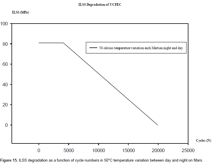
This extension can be accomplished by stretching the convex curves in a state that they represent more fatigue life. Because the temperature variation on LEO is at least 5.9 times of that on Mars, it is proposed that if the ILSS equation achieved by the convex curves method is equal to ILSS0 divided by 5.9, we might be able to illustrate how many thermal cycles on Mars ILSS is steady. But after the steady region, a new assumption is required. This theory states that, because of decreasing section of convex curves figures, there is an approximated linear part with negative slope (between 3000 to 4000 cycles); this slope can be divided by 5.9 (Temperature variation in LEO to Mars each night and day) to indicate the linear part for the Mars environmental condition. After these procedures, the linear part can be attached to the end of steady part. This process can be employed to derive the equations and figures for the ILSS and FM on Mars. The following results are obtained by this procedure. Based on these assumptions, if temperature variation on Mars is equal to 50°C, then for cycles between 4129 and 19907, ILSS is equal to

ILSS degradation is a function of Cycle numbers due to 50 Celsius temperature variation between day and night on Mars in UCFEC as illustrated in Figure 15.
Steady-linear method to obtain FM of UCFEC on Mars
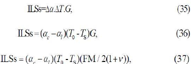
Obviously, because of reverse behavior between carbon fiber and epoxy due to their different coefficients of thermal expansion, there is always ILSs (inter laminar shear stress) between carbon fiber and epoxy. Thus, while the ILSS equation is equal to ILSs equation, the numerical value of fracture cycle number can be achieved. Furthermore, it is important to mention that the temperature variation in the following equation is the temperature difference from the sample’s crack free temperature. Crack free temperature is the temperature that the sample is uncracked. In the presented research, this temperature is 23°C (Anvari, 2014).
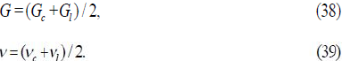
In the indicated Equations 36 and 37 that are achieved by application of Equation 35 (Maheswari and Prasad, 2013), FM is the Flexural Modulus of UCFEC, G is the shear modulus of UCFEC, and Gl is carbon fiber axial shear modulus.
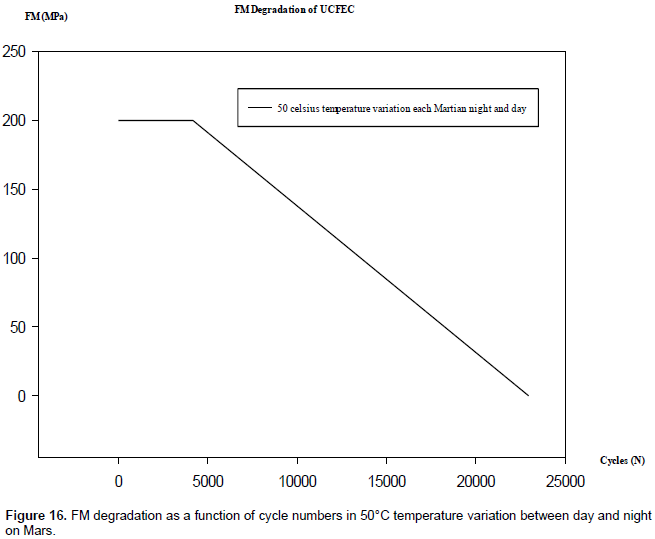
In Equation 39, ν is the Poisson’s ratio of UCFEC, νc is epoxy Poisson’s ratio, and νl is carbon fiber axial Poisson’s ratio. This is important to notice that, by applying the steady-linear approach, the FM equation on Mars is derived and shown in Figure 16. In order to develop this figure, FM convex curve is employed. Based on the results of steady-linear method, if the temperature variation on Mars between day and night is 50°C and cycle numbers are less than 4173, as a result, FM is equal to 199.8 MPa. Furthermore, by applying steady-linear method, it is obtained that, for cycle numbers between 4173 and 22951, the FM equation is
The above equation is obtained with the same method to derive the steady-linear equation for ILSS on Mars, but the only difference is that instead of using ILSS0, FM0 and instead of applying ILSS convex curve, FM convex curve is used.
Steady-linear method to obtain void volume in UCFEC on Mars
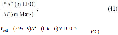
In order to obtain equations to estimate the void volume in UCFEC on Mars, it is assumed that before the numerical value of Nsteady =4129, that is, the Nsteady in ILSS equations for Mars environment, the void volume remains constant (void volume at zero cycle (Vvoid0) = 0.015). This assumption is based on the fact that because the ILSS in steady-linear method remains constant in these regions, the material properties and characteristics remain constant. Therefore, void volume remains the same numerical value ((Vvoid0) = 0.015). For the greater numerical quantities of Nsteady, by solving void volume equation (Equation 24) while it equals the relation (41), the numerical value for the fracture cycle on Mars, based on the void volume in UCFEC, can be obtained. The final cycle number to fracture on Mars (Nf), according to the void volume is 45224.

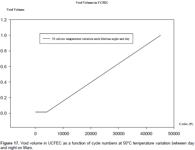
With the results available following the mentioned procedure, it is convenient to develop the steady-linear figure for the void volume as a function of cycle numbers. For the cycle number values less than 4129, the void volume in UCFEC remains constant (0.015) and for the greater cycle numerical quantities, the void volume increases to finally reach the maximum amount at 45224 cycle numbers. In figure 17, this process is observable. In order to develop the linear region equation in the following figure, two boundary conditions that represent two points, are as follow: N = 4129, Vvoid = 0.015 and N = 45224, Vvoid = 1. These two points are employed to create a relation, with two equations, two unknown quantities method. By following this method, there are
as a result of the above procedure, for the cycle numbers less than 4129, void volume is equal to 0.015, and if the cycle numbers are between 4129 and 45224, void volume equation is
In the linear region, 4129 Ë‚ N ≤ 45224, void volume growth rate that in this study is assumed to be equal to crack density growth rate is defined as
In Figure 17, void volume as a function of cycles in UCFEC for 50°C temperature variation each night and day on Mars is illustrated.
Applying steady-linear method
By applying Equation 48, the fatigue life of UCFEC on different seasons on Mars in night and day can be approximated. As previously obtained in this study, at 50°C temperature variation between night and day on Mars for cycle numbers 4129 to 19907, inter laminar shear strength function is:
In order to obtain the fatigue life at coldest winter night on Mars with the application of Equation 48, the following data are required. T0 = 150K (-123°C) at winter night on Mars (Pasachoff, 1993), the numerical values of αc and αl are indicated in Table 1, Ts = 23°C (crack free temperature) (Park et al., 2012), ν is the Poisson’s ratio of UCFEC obtained by Equation 39, G is the shear modulus of UCFEC obtained by Equation 38; and substituting Equations 34 and 40 into Equation 48, for ∆T (on Mars)=(TDay - TNight) = 50°C, Equation 48 can be changed into a new relation. By solving the mentioned relation, N is equal to 19891 cycles, that is, the fatigue life of UCFEC on coldest winter night on Mars. It is important to notice that the numerical value of (T0- Ts) in the relation is the maximum numerical value. Consequently, the Inter laminar shear stress is the maximum numerical amount, decreasing the fatigue life from 19907 cycles at zero ILSs to 19891 cycles at maximum ILSs. By employing Equation 48, this procedure can be repeated for all the temperatures on Mars in day and night in different seasons. With this method, by applying Equation 48, the fatigue life of UCFEC on Mars in all the temperatures can be evaluated.
FRACTURE IN UCFEC ON MARS DUE TO THERMAL FATIGUE
As proven previously, and based on Equation 48, since the temperature difference from 23°C (crack free temperature) is increased, the ILSs between carbon fiber and epoxy is increased. The temperature variation on Mars is from 150K (-123°C) to over 300K (27°C) (Pasachoff, 1993). Consequently, based on this knowledge, it appears that the temperature variations in winter is almost from 150K at winter night because of solar eclipse, to about 200K in winter day because of sun illumination in day. In autumn and spring, it is from almost 200K at night to about 250K in day. Additionally, in summer, temperature is from almost 250K at night to about 300K (27°C) in day.
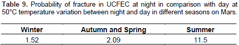
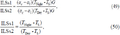
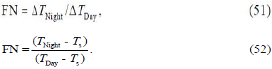
Based on these approximated conclusions, it is easy to estimate the probability of fracture for UCFEC on Mars night in comparison with Mars day in different seasons. By using relation (49), this estimation is possible. As concluded in Table 9, the probability of fracture at summer night is almost 11.5 times of summer days on Mars which is the maximum. The probability of fracture at coldest winter night is about 1.52 times of winter days, which is the minimum. This fact is concluded because the temperature at night is lower than the temperature in day and the maximum temperature at night on Mars is almost 250K. This implies that the variation of temperature from standard temperature in UCFEC (23°C) at nights is always greater than the variation of temperature in days. Thus, as the difference between the environmental temperature in Mars and UCFEC crack free temperature is increased, inter laminar shear stress is increased. Increase of inter laminar shear stress can be the cause of fracture in UCFEC because it can attain inter laminar shear strength of UCFEC. As proven by convex curves method, the main cause of fracture in UCFEC exposed to vacuum thermal cycles is due to degradation of inter laminar shear strength.

In relation (49), it can be concluded that for UCFEC, all the factors are related to material properties except the temperature variation from the standard temperature (Ts = 23°C). Consequently, the only factor that can affect the ILSs is the temperature variation because the temperature difference from the UCFEC uncrack temperature is the main cause in inducing inter laminar shear stress. Hence, it can be the main cause of fracture in UCFEC as proven by convex curves method.
fracture at nights (FN) can occur FN times in comparison with fracture in days in specific season.
In the Table 9, by applying mentioned relations, probabilities of fracture in UCFEC in Mars nights in comparison with Mars days in different seasons are indicated.
CARBON FIBER’S PARALLEL CRACK PROPAGATION METHOD
Multiple matrix cracks, also called intra laminar cracks, are observable in layer with off-axis orientation with respect to the main loading direction. These cracks are usually initiated in weakest positions or in stress concentration areas, as they cover the whole layer thickness and grow parallel to fibers in the layer (Giannadakis and Varna, 2009). During each loading cycle where the damage growth threshold is exceeded, the fiber/matrix interface crack will grow parallel to the fiber for a length da according to the crack growth law (Uleck, 2006).In this method, by using experimental data (Nakamura et al., 2007), the crack growth rate in Mars environment (50 Celsius temperature variation between day and night on Mars) is obtained and by applying the relation (55), the cycle numbers to fracture of UCFEC on Mars is approximately achieved.
Experimental procedures
To determine properties of present composite lamina, separate 8-ply specimens with unidirectional fiber were fabricated using the same vacuum bagging process. The thermal cycle tests were conducted using the environmental chamber. In the current experiments, in order to isolate the effects of thermal cycles, the rh was set at 0%. Total of five different amplitudes of ΔT = 140, 60, 30, 100, 120°C were prescribed during the measurement period. At initial phase, it took about 240 cycles to reach steady state propagation under ΔT = 140°C condition. During the steady state, the growth rate was estimated to be da/dN = 5.1 μm/cycle. At 500th cycle, the temperature amplitude was switched to 60°C and maintained for 100 cycles. The smaller number of cycles were chosen since it appeared that the propagation have reached the steady state much faster but at slower rate of about da/dN = 1.7 μm/cycle. In the subsequent phase (after 600 cycles), ΔT was reduced to 30°C. Even after 80 cycles, the measurements showed no visible change in the crack length (Nakamura et al., 2007).
Problem formulation
In Equation 53, L = 25 mm is the length of UCFEC sample, that is the length of carbon fiber as well. Lvoid is the void length in UCFEC sample that is equal to the length of sample multiplied by void volume defined in the following relation.
By following Equation 54, L2=24.625 mm is the effective length of UCFEC because 1.5% of the sample is the void volume. Using the interpolation between temperature variation 30°C and 60°C for da/dN, by applying the experimental data (Nakamura et al., 2007) mentioned previously, the da/dN= 1.133e-6 m/cycle for 50°C temperature variation between night and day on Mars is approximately obtained.
.png)
21734 cycle numbers to fracture in UCFEC is the cycle numbers to fracture at zero inter laminar shear stress between carbon fiber and epoxy. Thus, due to the fact that except the 23°C temperature (crack free temperature), at other temperatures on Mars there is always inter laminar shear stress between carbon fiber and epoxy. Hence, at temperatures except 23°C, the fracture occurs in a condition that ILSS is equal to ILSs. It means that fracture occurs at numerical values less than Nf = 21734 cycles. As a result, based on this approach, the fatigue life of UCFEC on Mars can be approximated less than 21734 cycles.
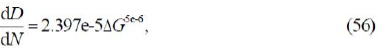
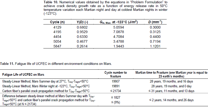
The following results in Table 10 is obtained by the same analytical method earlier used in “Problem Formulation” to obtain the results and Equation 28 in vacuum thermal cycles fatigue in LEO simulation experiment; however, in this part of study, the steady-linear method to provide the Mars data is employed. The following equation is derived by using the same method employed to derive Equation 28 in “Problem Formulation”. Equation 56 can be used to predict the thermal fatigue of UCFEC on Mars for 50°C temperature variation between night and day.
In Table 11, by using the Steady-linear method, the fatigue life of UCFEC in different seasons on Mars is approximated. Finally, the difference of cycle numbers to fracture between the steady-linear method and carbon fiber’s parallel crack propagation method is achieved.
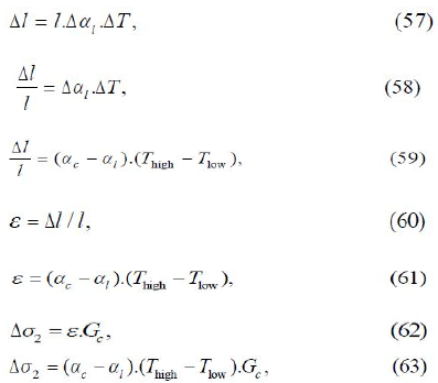
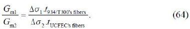
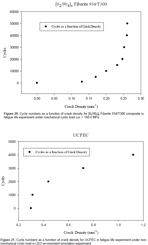
In the present part of the research, the results obtained for crack density growth rate as a function of energy release rate, are compared with the results of a fatigue life experiment for [02/904]s, Fiberite 934/T300 composite under mechanical cyclic load ∆Ï1 = 188.4 MPa. By using the data in Table 12, a relation for comparing the energy release rate between different fatigue life experiments is achieved. If the thickness of fibers in [02/904]s, Fiberite 934/T300 composite which has 6 fiber plies is considered 6 times of carbon fibers thickness in UCFEC which has 1 fiber ply; as a result, applying the following equations (by using Equations 57, 58, 60, and 62) (Maheswari and Prasad, 2013), to compare the energy release rate for different composites in fatigue life experiments under the different mechanical and non-mechanical cyclic loads, is proposed.
.png)

For UCFEC exposed to thermal cyclic load, there are the following equations to understand the role of thermal stress and strain in the presented study.
Therefore, the following relation can be suggested to compare the energy release rate in different cyclic load conditions.
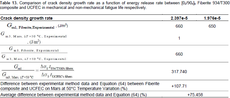
In the above Equations (57 to 64), αc is epoxy coefficient of thermal expansion; αA is carbon fiber axial coefficient of thermal expansion; Gc is epoxy shear modulus and ε is relative axial strain between epoxy and carbon fiber. In Figures, 18, 19, 20, 21, 22, and 23, crack density and crack density growth rate between [02/904]s Fiberite 934/T300 and UCFEC due to fatigue, are compared. Furthermore, in Table 13 comparison of crack density growth rate as a function of energy release rate between [02/904]s Fiberite 934/T300 composite and UCFEC in mechanical and non-mechanical fatigue life is indicated.
In the presented research, by applying analytical methods and using experimental data, equations to predict the fatigue life of UCFEC in LEO and Mars environments are achieved. This material (UCFEC) is one of the materials that is applied in aerospace structures like space crafts and satellites. The fatigue life that is estimated by these approaches is due to non-mechanical fatigue which is thermal cycles. In a part of the study, convex curves method to predict the fatigue life in LEO simulation experiment is obtained. The results of convex curves method have indicated that the main reason for fracture of UCFEC in LEO environment is the degradation of inter laminar shear strength between the carbon fiber and epoxy. In addition, by inspiration of convex curves method, the steady-linear method to predict the fatigue life in Mars environment is achieved. The results of convex curves method, steady-linear method, and other fatigue experiments for composite materials are compared. The comparisons have shown that the fatigue life prediction results of UCFEC seem correct. The results that are achieved by steady-linear method have proved that the longest life of UCFEC on Mars occurs in Martian summer day environment, and shortest life occurs at Martian winter night.
For future work, the effect of Martian atmosphere on the fatigue life of UCFEC is highly recommended because in this research the vacuum condition is being considered. This is of high importance because the Mars atmosphere including gases, water vapor, and other factors, might have an increasing or decreasing effect on fatigue life of UCFEC in Mars environment. The presented study including the future work proposal can significantly play an important contributive role in the upcoming spacecraft’s missions like the on-way human mission to Mars since predicting the thermal cyclic fatigue life is one of the most important issues that have to be considered for the space missions in order to achieve further space exploration.
The author has not declared any conflict of interests.
The author would like to appreciate the guidance of advisors. All the funding related to this study is provided by the presented author.
REFERENCES
|
Anvari A (2014). Fatigue life prediction of unidirectional carbon fiber/epoxy composite in Earth orbit. Int. J. Appl. Math. Mech. 10(5):58-85.
|
|
|
|
Anvari A (2016). Friction coefficient variation with sliding velocity in copper with copper contact. Periodica Polytechnica, Mechanical Engineering. 60(3):137.
|
|
|
|
|
Anvari A (2017). Crack growth as a function of temperature variation in carbon fiber/epoxy. J. Chem. Eng. Mater. Sci. 8(3):17-30.
Crossref
|
|
|
|
|
Anvari A (2017). Effect of nano carbon percentage on properties of composite materials. J. Chem. Eng. Mater. Sci. 8(4):31-36.
|
|
|
|
|
Anvari A (2017). Failure of Nickel-base super alloy (ME3) in aerospace gas turbine engines. J. Chem. Eng. Mater. Sci. 8(6):46-65.
Crossref
|
|
|
|
|
Adibnazari S, Anvari A (2017). Frictional effect on stress and displacement fileds in contact region. J. mech. eng. res. 9(4):34-45.
|
|
|
|
|
Biro T, Csizmadia J (2012). recent technique for thermal-fatigue simulation of heat-resistant steels. periodica polytechnica, Mechanical Engineering. 56(2):107-112.
|
|
|
|
|
Diego A, Charles UR (2014). Symposium keynote: Enduring the isolation of interplanetary travel a personal account of the Mars500 mission. Acta Astronautica. 93:374-383.
Crossref
|
|
|
|
|
Des Marias DJ (2010). Exploring Mars for Evidence of Habitable Environments and Life. Proceeding of the American philosophical society. 154(4):402-422.
|
|
|
|
|
Fujita K, Ozawa T, Okudaira K, Mikouchi T, Suzuki T, Takayanagi H, Tsuda Y, Ogawa, N, Tachibana S, Satoh T (2014). Conceptual study and key technology development for Mars Aeroflyby sample collection. Acta Astronautica. 93:84-93.
Crossref
|
|
|
|
|
Funk JG, Sykes GF (1989). The effects of simulated space environmental parameters on six commercially available composite materials. NASA Technical Paper 2906. Washington DC: National Aeronautics and Space Administration.
|
|
|
|
|
Gao Y, He S, Yang D, Liu Y, Li Z (2005). Effect of vacuum thermo-cycling on physical properties of unidirectional M40J/AG-80 composites. Compos. Part B: Eng. 36:351-358.
Crossref
|
|
|
|
|
Giannadakis K, Varna J (2009). Effect of thermal aging and fatigue on failure resistance of aerospace composite materials. 5th International EEIGM/AMASE/FORGEMAT conference on Advanced Materials Research, IOP Conf. Series: Materials Science and Engineering 5, 012020:1-9.
Crossref
|
|
|
|
|
Guo W, X ue P, Yang J (2013). Nonlinear progressive damage model for composite laminates used for low-velocity impact. Applied Mathematics and Mechanics (English Edition). 34(9):1145-1154.
Crossref
|
|
|
|
|
Harris BED (2003). Fatigue in Composites. Woodhead Publishing Limited, Cambridge, UK.
|
|
|
|
|
Hertzberg RW (1989). Deformation and Fracture Mechanics of Engineering Materials. Wiley. 467.
|
|
|
|
|
Karadeniz ZH, Kumlutas D (2007). A numerical study on the thermal expansion coefficients of fiber reinforced composite materials. Master of science Thesis in mechanical engineering, Energy program, Dokuz Eylul University.
|
|
|
|
|
Liu S, Nairn JA (1990). Fracture mechanics analysis of composite microcracking: Experimental results in fatigue. Proceeding of the 5th Technical Conference on Composite Materials, American Society of Composites, East Lansing, Michigan 6:287-295.
|
|
|
|
|
Maheswari TS Uma, Prasad P Hari (2013). Reliability of Thermal strain and stresses in simple bars. IOSR J. Math. 5(2):05-09.
|
|
|
|
|
Malekzadeh Fard K, Monfared MM, Norouzipour K (2013). Determination of stress intensity factor in half-plane containing several moving cracks. Applied Mathematics and Mechanics (English Edition). 34(12):1535-1542.
Crossref
|
|
|
|
|
McEwen AS (2013). The surface of Mars chenges all the time. Is flowing water one of the causes? Scientific American.
|
|
|
|
|
Meszaros L, Turcsan T (2014). Development and mechanical properties of carbon fibre reinforced EP/VE hybrid composite systems. periodica polytechnica, Mechanical Engineering. 58(2):127-133.
|
|
|
|
|
Mohlmann D, Thomsen K (2011). Properties of cryobrines on Mars. Icarus. 212:123-130.
Crossref
|
|
|
|
|
Nakamura T, Ramanujam N, Vaddadi P, Singh RP (2007). Interlaminar Fatigue Growth under Thermal Cycles in Composite Laminate. 16TH International Conference on Composite Materials, Kyoto, Japan.
|
|
|
|
|
Pan SD, Zhou ZG, Wu LZ (2013). Basic solutions of multiple parallel symmetric mode-Ó€Ó€Ó€ cracks in functionally graded piezoelectric/piezomagnetic material plane. Applied Mathematics and Mechanics (English Edition). 34(10):1201-1224.
Crossref
|
|
|
|
|
Park SY, Choi HS, Choi, WJ, Kwon H (2012). Effect of vacuum thermal cyclic exposures on unidirectional carbon fiber/epoxy composites for low earth orbit space applications. Composites: Part B. 43:726-738.
Crossref
|
|
|
|
|
Pasachoff JM (1993). From the Earth to the Universe. Part 2: The Solar System, 11 Mars, Saunders College Publishing, Williamstown, Massachusetts, Fourth Edition, 190-203.
|
|
|
|
|
Salotti JM (2011). Simplified scenario for manned Mars missions. Acta Astronautica. 69:266-279.
Crossref
|
|
|
|
|
Salotti JM (2012). Revised scenario for human missions to Mars. Acta Astronautica. 81(1):273-287.
Crossref
|
|
|
|
|
Suhir E (2012). Human-in-the-loop: likelihood of vehicular mission¬success-and-safety. J. Aircr. 49(1):29-36.
Crossref
|
|
|
|
|
Salotti JM, Suhir E (2014). Manned missions to Mars: Minimizing risks of failure. Acta Astronautica. 93:148-161.
Crossref
|
|
|
|
|
Schulze-Makuch D, Davies P (2010). To Boldly Go: A One-Way Human Mission to Mars. J. Cosmology. 12:3619-3626.
|
|
|
|
|
Shin KB, Kim CG, Hong CS, Lee HH (2000). Prediction of failure thermal cycles in graphite/epoxy composite materials under simulated low earth orbit environments. Compos Part B: Eng. 31:223–235.
Crossref
|
|
|
|
|
Song K, Zhang Y, Meng J, Green EC, Tajaddod N, Li H, Minus ML (2013). Structural Polymer-Based Carbon Nanotube Composite Fibers: Understanding the Processing Structure-Performance Relationship. Materials. 6:2543-2577.
Crossref
|
|
|
|
|
Sendeckyj GP (1990). Life prediction for resin-matrix composite materials, (Reifsnider, K.L., editor). Fatigue of Composite Materials. Elsevier Science Publishers, 431-483.
|
|
|
|
|
Uleck KR (2006). A Hybrid Model for Fatigue Life Estimation of Polymer Matrix Composites. Ph.D. thesis, University of Maryland: 108.
|
|
|
|
|
Voicu R (2012). Structural Characterization and Mechanical Behaviour of Carbon Fiber/epoxy Composite for Aeronautical Field. Materiale Plastice. 49(1):34-40.
|
|


.png)
.png)