ABSTRACT
The main objective of this paper is to develop a method to predict the crack length and crack growth rate in unidirectional carbon fiber/epoxy composite as a function of temperature variation. In order to measure the crack length and crack growth rate, a new analytical method by applying experimental procedure data is developed. By the novel analytical method, relations are achieved to predict the crack length and crack growth rate in unidirectional carbon fiber/epoxy composite. Finally, by using these relations, comparison between crack length and crack growth rate between two thermal fatigue experiments is done. The results have shown that the crack growth rate in bidirectional carbon fiber/epoxy composite is very higher that in unidirectional carbon fiber/epoxy composite. Investigations regarding the achieved results have shown that the higher crack growth rate is due to the mismatch between the coefficients of thermal expansion in two directions of bidirectional carbon fiber/epoxy composite. The two different coefficients of thermal expansion may cause stress concentration in the inter-laminar plies of the composite and therefore may cause higher crack growth rate.
Key words: Crack growth rate, thermal fatigue, temperature variation, carbon fiber, epoxy, composite material.
Since the birth of polymer science in the 1930s, these materials have dominated the market in terms of their versatility for product applications. These materials have been utilized in the form of films, fibers, sheets, and coatings. Today, most of the synthetic polymer fibers in use span applications such as clothing, carpets, ropes, and reinforcement materials (Song et al., 2013).
Carbon fiber is defined as a fiber containing at least 92 wt% carbon, while the fiber containing at least 99 wt% carbon is usually called a graphite fiber. Carbon fibers generally have excellent tensile properties, low densities, and high thermal and chemical stabilities in the absence of oxidizing agents, good thermal and electrical conductivities, and excellent creep resistance. They have been extensively used in composites in the form of woven textiles, prepregs, continuous fibers/rovings, and chopped fibers (Huang, 2009).
In recent years, the carbon fiber industry has been growing steadily to meet the demand from different industries such as aerospace (aircraft and space systems), military, turbine blades, construction (non-structural and structural systems), light weight cylinders and pressure vessels, off-shore tethers and drilling risers, medical, automobile, sporting goods, etc (Huang, 2009).
As designers push for increased performance, there is an evident need for advanced multi- functional materials. Carbon fiber composites are of particular interest for the automotive and aerospace industries for their high strength, lightweight, and high stiffness. These characteristics make carbon fiber composites one of the most advanced materials to date. However, it does have a few significant drawbacks: matrix dominate fatiguing, compressive strength, electrical and thermal conductivity. It is believed that these characteristic can be improved upon with functionalized carbon nanotubes. Under fatigue loading the final failure will be a result of either complete fiber fracture (fiber dominate) or buckling (matrix dominate). In woven carbon fiber reinforced polymers, CFRP, a number of damage modes occur before this final failure. Previous investigations have shown debonding of fiber-matrix interface, fiber breakage, normal and longitudinal matrix cracking under tension-tension and tension-compression loading (Wilkerson et al., 2007).
Composites are materials widely used lately in the aeronautical industry to manufacture several parts as flaps, aileron, landing-gear doors and others. Polymer matrix composite materials constituted by continuous carbon fibers embedded in a thermosetting epoxy resin were first developed to satisfy high standards required in aircraft design. Compared to metals the epoxy/carbon composites offer similar or better mechanical properties by mixing in these two distinct phases, fibers and resin, and adopting different fiber configurations (Voicu, 2012). Further investigation on composite materials properties are also performed by Chow et al. (2016), Meszaros and Turcsan (2014), and Jo and Lee (2014).
As it is mentioned in the previous paragraphs, in recent years, due to the increase of applying carbon fiber/epoxy composite (CFEC) in many industries like aerospace, the need of accurate evaluation of life for this material can be sensed. Estimation of life is of high importance in predicting the reliability and safety of different materials in different environmental conditions. In a significant and vital industry like aerospace, estimating life of aerospace structures materials is undeniable. As it is clear, there are many people in aerospace vehicles traveling to different parts of earth or space and that makes the safety for the aerospace structures very vital. CFEC is one of the materials that can be used in aerospace vehicles structures. Therefore, prediction of its safety in air and space is undeniable in order to have a safe aerospace structure and saving human lives boarding on it. Fatigue life prediction is part of a safety plan for aerospace vehicles.
Moreover, in space vehicles due to temperature variation from sun illumination to solar eclipse, a high thermal cycle can be created. These thermal cycles can lead to a thermal fatigue that can seriously cause deterioration and damage in space vehicle or satellite and develop cracks in their structures. Satellites are the great examples for the thermal fatigue since they are rotating around the planets and consequently, they experience thermal cycles while traveling from planets’ shadows through the sunlight exposure locations. In order to predict the long-term durability, recently, crack closure detection using photometrical analysis is submitted by Savkin et al. (2015) and durability and integrity studies of environmentally conditioned interfaces in fibrous polymeric composite: critical concepts and comments is provided by Ray and Rathore (2014).
In assessment of the damage in different materials, canary approach for monitoring BGA interconnect reliability under temperature cycling is presented by Chauhan et al. (2012), thermal fatigue and hypothermal atomic oxygen exposure behavior of carbon nanotube wire is provided by Misak et al. (2013), and determination of material parameters for discrete damage mechanics analysis of carbon-epoxy laminates is developed by Barbero and Cosso (2014).
Some of the cited studies have investigated the fatigue life of composite laminates. Nevertheless, it appears that there are a few works in this area that can clearly illustrate the thermal deterioration in any environmental conditions. Furthermore, it seems that there is no work to present a relation that illustrates the crack growth rate as a function of temperature variation in UCFEC.
In the presented research, by applying an experimental procedure and using a new analytical method, relations to predict the cracks propagation of UCFEC in various temperature variations have achieved. The results of this contribution can be applied for estimation of crack growth rate in UCFEC in different temperature variations.
The thermal cycling tests were conducted by using a thermal vacuum chamber (Hanchang Eng, South Korea), as shown in Figure 1A. The experiment was performed in an environmental cham- ber with a proportional integral derivative (PID) programmable temperature controller. Test temperature range should be as large as practicable to meet environmental stress screening (ESS) purposes based on the guideline in MIL–STD-810F and MIL-STD1540C. It is generally required to reveal potential flaws in material exposed to more extreme temperature change condition. In this study, extreme temperature conditions (120 to -175°C) encompass an environmental severity over that expected during service life based on the previous studies. Common to each of the thermal cycling profiles, low temperature (Tlow = -175 ± 5°C) simulates the solar eclipse condition and cycle-specific high temperature (Thigh = 120 ± 5°C) corresponds to the sun illumination for each 2 min duration time, as shown in Figure 1B (Park et al., 2012). Following this profile, one cycle was designed as the sequence from 120 to -175°C and back to 120°C so that the total duration of each cycle was approximately 43 min. A vacuum pressure of 1.3-3 Pa was employed throughout the thermal cycling test (Park et al., 2012).
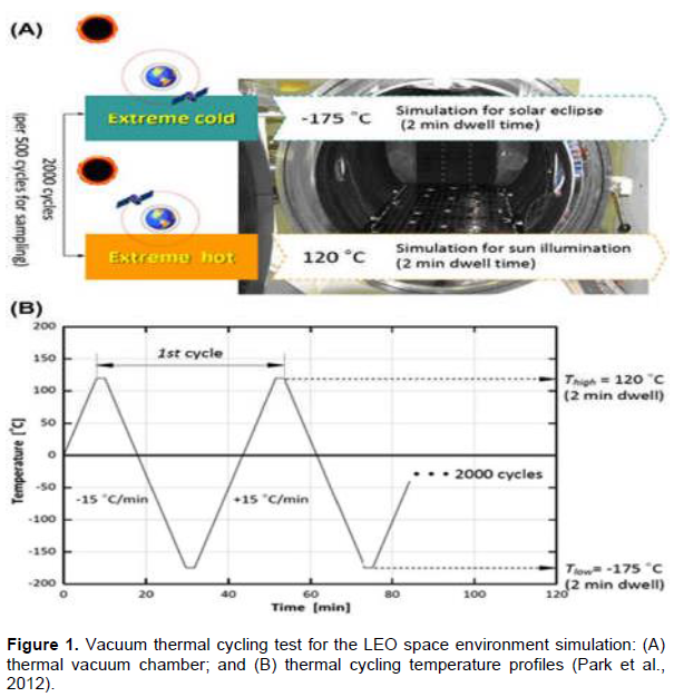
The extent of degradation was determined experimentally by exposing the test panels to vacuum thermal cycling. The experiments were repeated for 500 cycles (358 h), 1000 cycles (716 h), 1500 cycles (1074 h) and 2000 cycles (1432 h). Following the thermal cycling exposure, all partly-or fully-aged test panels were cut into the desired dimensions using a water-cooled diamond saw and subsequently dried in a vacuum oven at 60°C for 24 h to remove moisture after the cutting operation. Series of physical and mechanical tests were then performed in the standard laboratory atmosphere of 23 ± 2°C and 50 ± 5% relative humidity on the baseline (unaged) and environmentally conditioned test samples (Park et al., 2012).
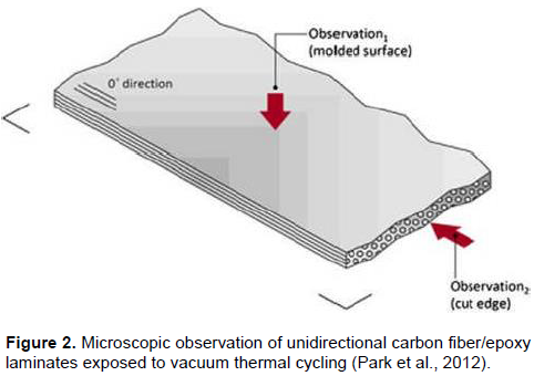
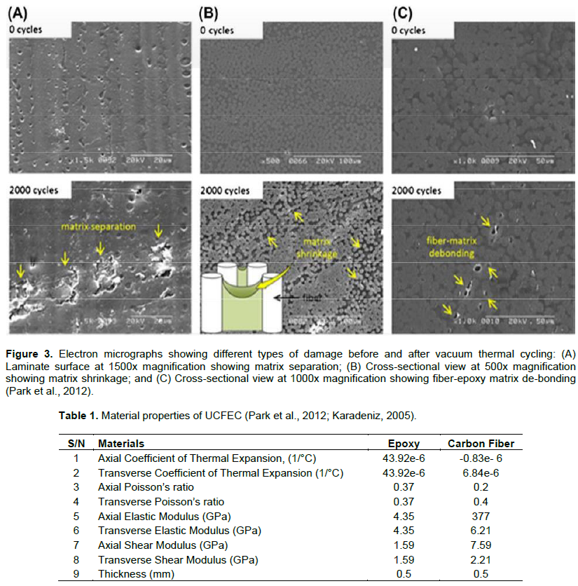
In Figure 2 (Park et al., 2012), the sample of UCFEC that is used in simulation experiment of LEO environment is shown. In the following parts of paper, by the existing assumption in LEO environment, and material properties of UCFEC, rate of crack density growth can be obtained. In Table 1, the material properties of UCFEC are indicated.
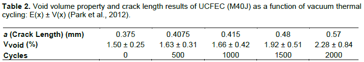
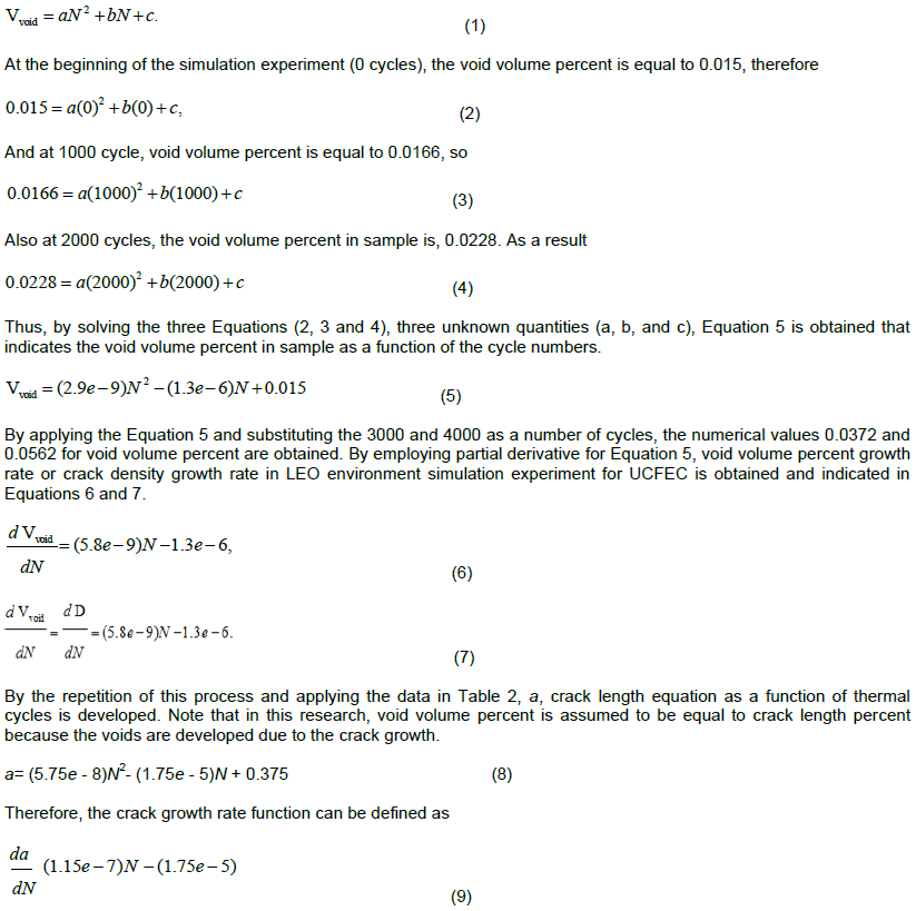
In Table 2, the void volume percent in (M40J) UCFEC for the cycles 0, 500, 1000, 1500, and 2000 in LEO simulation experiment are shown. By using these data from Table 2, an equation to obtain the void volume percent in any cycle is possible. This equation indicates the void volume percent in UCFEC as a function of cycle numbers. By using this equation, and by applying partial derivative, obtaining the numerical value of void volume percent growth rate is possible. In this research, the void volume percent growth rate is assumed to be equal to crack density growth rate because it seems that the only void volume growth rate is due to crack density growth rate. It is noticeably; the function of crack density growth rate that obtained in this paper (equation (7)) indicates approximately the maximum of possible crack density growth rate.
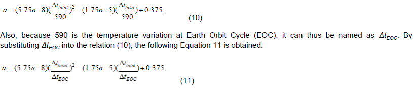
and because each cycle is temperature variation from 120 to -175°C and back to 120°C (Park et al., 2012); subsequently, each cycle becomes 590°C temperature variation. Therefore, 1 Celsius temperature variation is 1/590 of each cycle. Moreover, Δt Celsius temperature variation may be referred as Δt/590.
By imposing this result into Equation 8, Equation 10 can be developed. Equation 10 illustrates the crack length as a function of temperature variation.
In this part of paper, a method for fatigue life prediction of UCFEC in LEO environment simulation experiment, by applying an analytical approach and by using the experimental results is achieved. The experimental results that are used to develop the Convex Curves Method are obtained from vacuum thermal cyclic exposures (Park et al., 2012). In this method, by considering the data from experimental results and finding the points that develop convex curves, numbers of functions to predict the fatigue life of UCFEC are obtained.
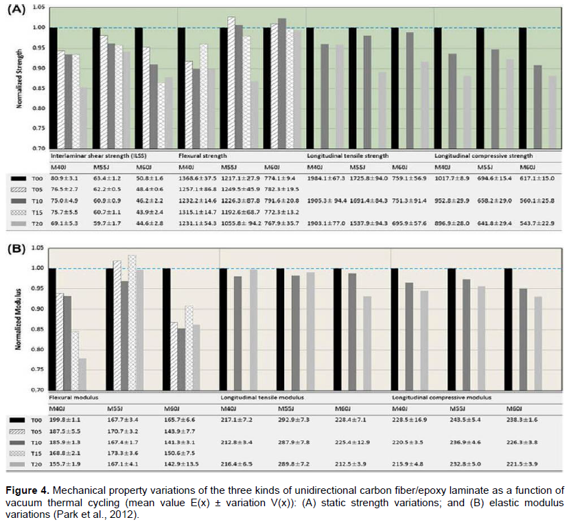
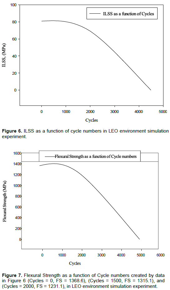
Figure 4 (Park et al., 2012) indicates the results of LEO environment simulation experiment after elapsing 0, 500, 1000, 1500, and 2000 of vacuum thermal cycles. The functions that are obtained from these results are useful to predict the fatigue life of UCFEC in satellite or space application, since UCFEC can be used in the structures of satellites and space crafts. In Figure 4, there are many data for inter-laminar shear strength (ILSS), flexural strength, flexural modulus, and so on. In order to use the convex curves approach, for example in ILSS, Figure for M40J, by using the three points (Cycles = 0, ILSS = 80.9), (Cycles = 1500, ILSS = 75.7), and (Cycles = 2000, ILSS = 69.1), and by solving three equations, three unknown quantities, like the method that is used to develop equation (5), a convex curve is developed. This convex curve in a determined coordinate can intersect the cycle axis at zero ILSS. It means that, the numerical value of the cycle number that is achieved by this method can indicate the fatigue life of the UCFEC in LEO environment. This process to find more convex curves to predict the fatigue life is repeated. For the material M40J which is a UCFEC only three convex curves: ILSS, flexural strength (FS), and flexural modulus (FM), from the data of the Figure 4 (Park et al., 2012) is obtained. The other data for M40J, such as longitudinal tensile strength, longitudinal compressive strength, longitudinal tensile modulus, and longitudinal compressive modulus can develop concave curves which might never intersect the cycle axis, so it seems, predicting the cycle number to failure by employing the concave curves can be impossible.
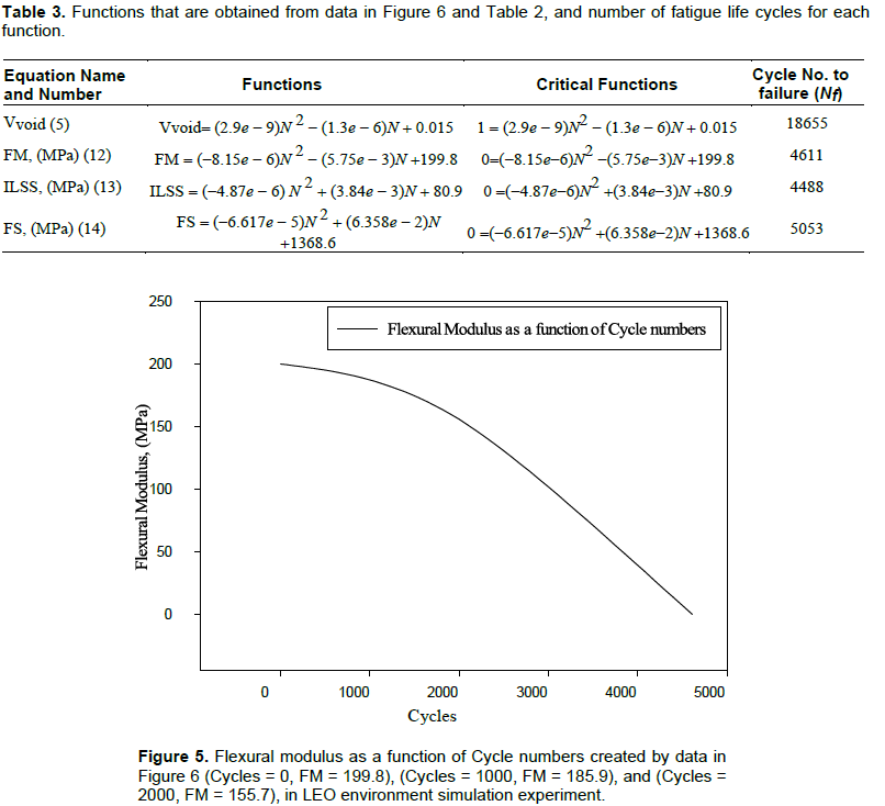
In Table 3, the functions of convex curves that are obtained by this analytical method are indicated and are shown in Figures 5 to 7. By solving the Equation 12 while it equals to zero, a cycle number to FM failure is obtained, by solving the Equation 13 while it is equal to zero, a cycle number to ILSS failure is achieved, and by solving the Equation 14 while it equals to zero, a cycle number to FS failure is obtained. The cycle numbers for each failure are indicated in Table 3. It appears that the most likely fracture state is the fracture state of ILSS because the cycle number to failure for this state is the minimum cycle number.
Convex curves method analysis
As it is obvious in Table 3, the minimum cycle numbers of fatigue life is due to ILSS. It means that, the cause of failure in UCFEC can be due to degradation in ILSS. In order to investigate the fracture process, it is reasonable to conclude that, as it seems that the result of degradation in ILSS is the main cause of fracture, it
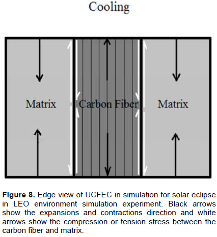
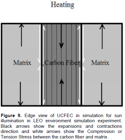
appears that the matrix de-bonding of UCFEC is the main cause of fracture. So, based on the convex curves method analysis, de-bonding between carbon fibers and epoxy is the most likely state of fracture. Thus, it appears it is right to conclude that, because the number of cycle to failure that is obtained due to degradation of flexural modulus is greater than the number of cycle to failure due to degradation of ILSS, so, it’s a second probable mode of fracture. Again it is concluded that, third probable state of fracture is due to the flexural strength degradation of UCFEC because the cycle number to failure for this state is greater than the cycle number to failure due to degradation of flexural modulus. In Figures 8 and 9, the fracture phenomenon due to the degradation of UCFEC’s ILSS exposed to vacuum thermal cycles is shown.
Fracture process analysis
As has been proven, it seems that the most likely state of fracture for UCFEC in LEO simulation experiment is the fracture duo to the degradation of ILSS. Vacuum thermal cyclic fatigue which is a non-mechanical fatigue is the main cause to failure in LEO environment. Therefore, to analyze the fracture process, a thermal analysis is necessary. As the temperature is raised from 23 to 120°C, due to longitudinal coefficient of thermal expansion for carbon fiber and epoxy which are negative and positive respectively, carbon fiber is tended to contract in longitudinal axis but epoxy is tended to expand in longitudinal axis. In this state, carbon fiber is withstood tensile force and epoxy is withstood compressive force. While the temperature decreases from 23 to -175°C, the epoxy withstood tensile force and the carbon fiber withstood compressive force. Because the carbon fiber and epoxy are stuck together, due to this reverse behavior of carbon fiber and epoxy in longitudinal direction, cracks are induced especially in the interface-bonding surface between fiber and matrix. By continuing the thermal cycles, the cracks are propagated and by the propagation of cracks, ultimately, the fracture is occurred.
In the presented part of this study, the results of this research are compared with the results of another experiment. In the comparison of these two results, mostly, crack growth rate as a function of temperature variation have been investigated. Both experiments are thermal fatigue experiments on CFEC. Nevertheless, the first experiment is being done on unidirectional CFEC (Park et al., 2012), but the second experiment is being performed on bidirectional CFEC (Ramanujam et al., 2008).
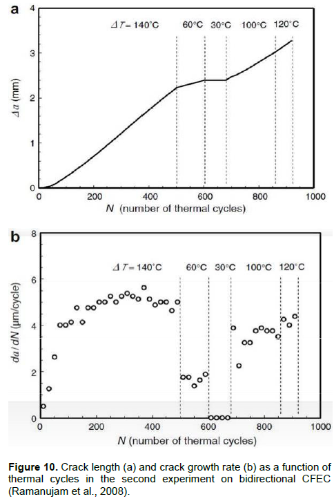
For the first experiment, a procedure to achieve the crack growth rate as a function of temperature variation is introduced and for the second experiment (Ramanujam et al., 2008), data for crack growth rate as a function of different temperature variations are available from the experiment data. In the following figure, the number of thermal cycles and temperature variation related to those are illustrated. In the following relations, by using Figure 10, the total temperature variation is obtained.
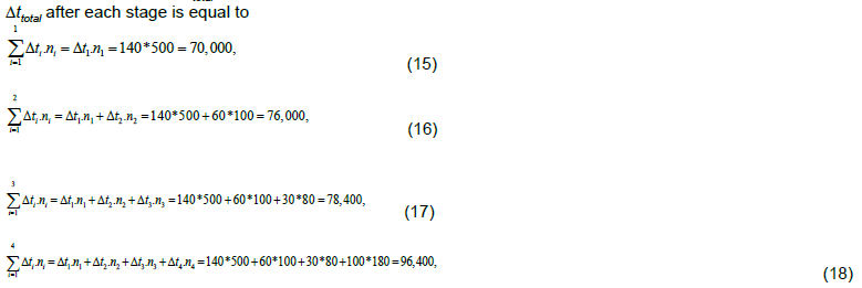
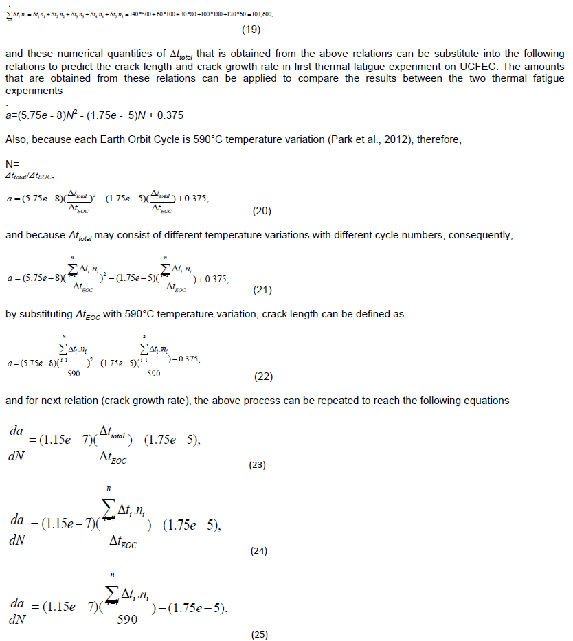
As observed in Figure 10, in the second thermal fatigue experiment on Bidirectional CFEC, there are five stages including different temperature variations and cycles at each of them. Therefore, in order to calculate the total temperature variation (∆ttotal) at each point of the second experiment, the following relations are suggested. As a result, ∆ttotal after each stage is equal to
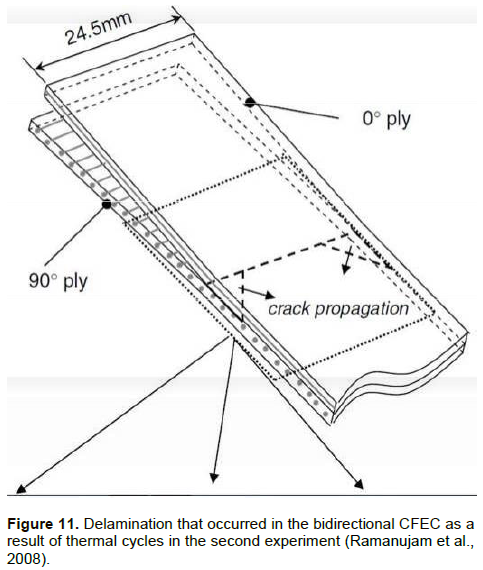
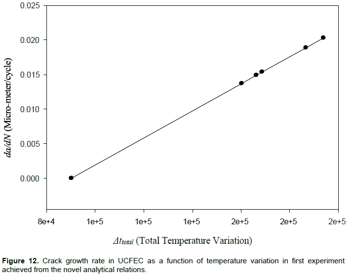
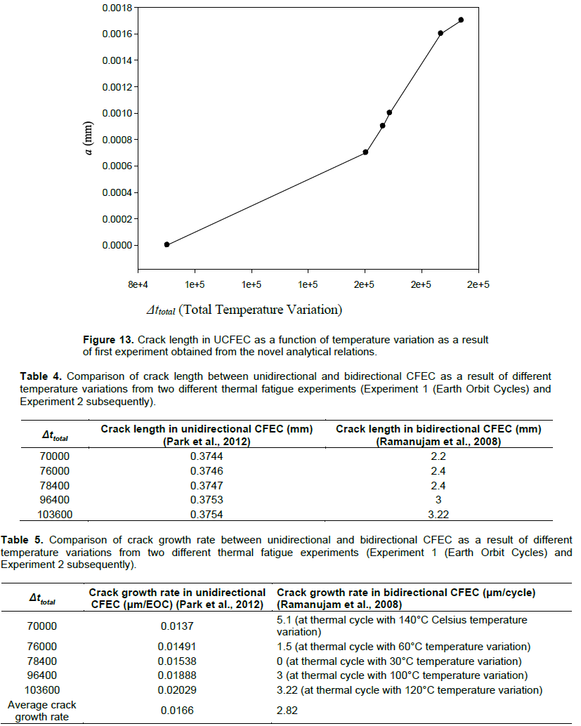
In Figure 11, delamination occurred in the bidirectional CFEC as a result of thermal cycles in the second experiment is shown. Furthermore, the results of this research are illustrated in Figures 12 and 13. Moreover, comparisons obtained from the results of this study are indicated in Tables 4 and 5.
In the presented study, an investigation to predict the crack growth rate as a function of temperature variation for UCFEC is done. In doing this process, by using experimental procedure data and applying new analytical method, equations are developed. These novel equations can illustrate the crack growth rate as a function of temperature variation. Finally, the comparison of crack growth as a function of temperature variation between UCFEC and bidirectional CFEC is done. By comparison, it appears that crack growth rate as a function of temperature variation in bidirectional CFEC is more than 169 times of that in UCFEC. It seems that the reason might be due to mismatch between coefficients of thermal expansion in both direction for bidirectional CFEC; because difference between coefficients of thermal expansion in both direction can develop more stress concentration in the inter-laminar plies. Higher stress concentration may cause higher crack growth rate in the composite material and consequently, cause larger crack propagations rate especially in the epoxy.
The authors have not declared any conflict of interests.
REFERENCES
|
Barbero EJ and Cosso FA (2014). Determination of Material Parameters for Discrete Damage Mechanics Analysis of Carbon-Epoxy Laminates. Composites: Part B 56:638-646.
Crossref
|
|
|
|
Chauhan P, Osternman M, Pecht M (2012). Canary Approach For Monitoring BGA Interconnect Reliability Under Temperature Cycling. CALCE Electronic Products and Systems Center, University of Maryland, College Park, MD 20742.
|
|
|
|
Huang X (2009). Fabrication and Properties of Carbon Fibers. Materials 2:2369-2403.
Crossref
|
|
|
|
Jo HS, Lee GW (2014). Thermal Expansion Coefficient and Young's Modulus of Silica- Reinforced Epoxy Composite. Int. J. Chem. Mol. Nucl. Mater. Metallurgical Eng. 8(11):1188-1191.
|
|
|
|
Karadeniz ZH (2005). A numerical study on the thermal expansion coefficients of fiber reinforced composite materials. Master of Science Thesis in mechanical engineering, Energy Program, Dokuz Eylul University.
|
|
|
|
Meszaros L, Turcsan T (2014). Development and mechanical properties of carbon fibre reinforced EP/VE hybrid composite systems. Periodica Polytechnica, Mec. Eng. 58(2):127-133.
|
|
|
|
Misak HE, Sabelkin V, Mall S, Kladitis PE (2013). Thermal fatigue and hypothermal atomic oxygen exposure behavior of carbon nanotube wire. Carbon 57:42-49.
Crossref
|
|
|
|
Park a,* SY, Choi b HS, Choi a WJ, and Kwon a H 2012). Effect of vacuum thermal cyclic exposures on unidirectional carbon fiber/epoxy composites for low earth orbit space applications. Composites: Part B 43, pp. 726-738.
|
|
|
|
Ramanujam N, Vaddadi P, Nakamura T, Singh RP (2008). Interlaminar fatigue crack growth of cross-ply composites under thermal cycles. Composite Structures 85:175-187.
Crossref
|
|
|
|
Ray BC and Rathore D (2014). Durability and integrity studies of environmentally conditioned interfaces in fibrous polymeric composites: Critical concepts and comments. Department of Metallurgical and Materials Engineering, National Institute of Technology, Rourkela-769008, India.
Crossref
|
|
|
|
Savkin A, Andronik A, Abhilash R (2015). Crack Closure Detection Using Photometrical Analysis. Periodica Polytechnica, Mech. Eng. 59(3):114-119.
|
|
|
|
Song K, Zhang Y, Meng J, Green EC, Tajaddod N, Li H, Minus ML (2013). Structural Polymer-Based Carbon Nanotube Composite Fibers: Understanding the Processing Structure-Performance Relationship. Materials 6:2543-2577.
Crossref
|
|
|
|
Voicu R (2012). Structural Characterization and Mechanical Behaviour of Carbon Fiber/epoxy Composite for Aeronautical Field. Materiale Plastice 49(1):34-40.
|
|
|
|
Wilkerson J, Daniel A, and Daniel D (2007). Fatigue Characterization of Functionalized Carbon Nanotube Reinforced Carbon Fiber Composites. Texas A & M University, college station, Texas 77844-3012.
|