ABSTRACT
This paper presents a two-way comparison between a stitched transmission line constructed with a copper wire and conductive thread, and a stitched transmission line constructed with conductive threads only from Light Stitches®. The stitched transmission lines which are both 150 mm long consist of a copper inner conductor surrounded by a tubular insulating layer made up of polyethylene. For shielding purpose, the structure is stitched onto a 150 mm × 150 mm denim material first with a copper wire and a conductive thread and secondly with conductive threads only, with stitch lengths, thread tension and stitch width at 2, 4 and 2 mm, respectively. The direct current (DC) resistances of the stitched transmission lines were measured to compare DC losses, while the scattering parameters were investigated through simulation and experiments within a frequency range of 0.04 to 4 GHz with results demonstrating an improved transmission characteristic and less DC loss with the stitched transmission line with copper wire and conductive thread.
Key words: Stitched transmission line, conductive thread, copper wire, direct current (DC) resistance, S-parameters, stitch length, thread tension, stitch width.
Textile transmission lines have been developed and used as means for transmitting signals to and from wearable devices over the last decade, with extensive characterisation for use in wearable computing applications. Unlike conventional transmission lines, textile transmission lines are wearable as they are washable, flexible, lightweight, robust and comfortable (Chedid et al., 2007). In addition to being used in connecting antennas to transmitters and receivers, textile transmission lines can also be used to connect communication equipment used in transmitting measurement data that can be continuously used to monitor the health status of patients. Methods of implementing textile transmission lines have been presented by LeÅ›nikowski (2011), while studies on textile transmission lines have been conducted in Xu et al. (2014), LeÅ›nikowski (2015), Locher et al. (2004), Merritt et al. (2005), Cottet et al. (2003), Kirstein et al. (2002), Locher and Tröster (2007), Jeon et al. (2011) and Choi and Kim (2016). Until recently, Isaac et al. (2017) presented a stitched transmission line for broadband applications, using the idea of a braided coaxial cable. The proposed stitched transmission line which is very practical, economical, fast and easy to install has sufficient frequency range to support multiple channel transmission.
Attenuation is the intrinsic power loss within a transmission line, which is dependent both on the transmission line design and on frequency and length of the transmission line. For coaxial cables, attenuation is found to also increase over a period of time due to flexing and inflow of moisture into the cable. However, it is most affected by DC resistance of the conductor. Conductive threads, when used as transmission lines, tend to have more losses compared to metallic conductors because of their resistance. This article presents stitched transmission lines constructed with copper wires and conductive threads and with conductive threads only. The idea of using both conductive threads and copper wires in the fabrication of the stitched transmission line was employed to appreciate its effect on the DC resistance of the stitched transmission line and the prospect of minimising DC losses.
DESIGN AND CONSTRUCTION OF THE STITCHED TRANSMISSION LINE
Numerical modelling
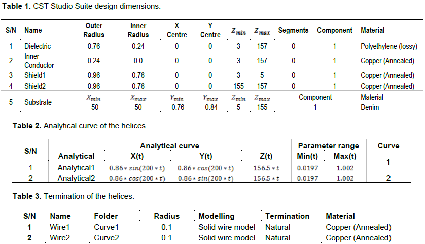
The stitched wearable transmission line was modeled as a composite counter wound helical structure with a concentric conductor as proposed by Wait (1976) as shown in Figure 1. The design was carried out with CST Microwave Studio Suite®, which is an electromagnetic simulation software that uses fast and memory efficient Finite Integration Technique (FIT) method and comprises of tools for the design and optimization of devices operating in a wide range of frequencies - static to optical.
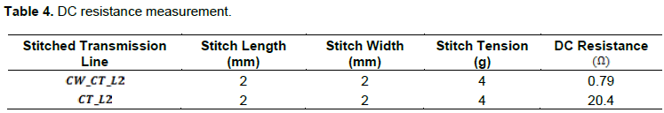
The stitched transmission design consists of an inner conductor made up of annealed copper, surrounded by a polyethylene (PE) insulating layer, a double helix annealed copper shield and a denim substrate on which the stitched transmission line is stitched. To model the shield which is made up of two helices, the analytical curve was used which gives the option of having either the solid wire model to be natural or rounded. Here the natural solid wire was chosen, with the design dimensions chosen as that of an RG174 braided coaxial cable (Tables 1, 2 and 3 for design dimensions)..
Fabrication of the stitched transmission line
The stitched transmission line was constructed using a sewing machine, with the aid of a novel presser foot having a stitch length of 2 mm, stitch width 2 mm and its tension set at 4.
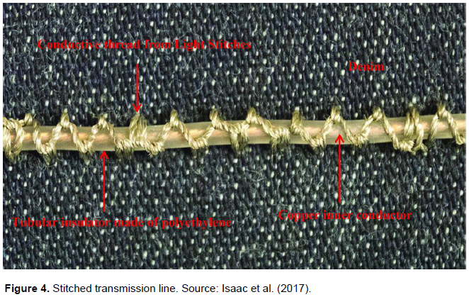
To construct the stitched wearable transmission line, an RG 174 braided coaxial cable was stripped of its outer jacket and shield leaving behind the inner conductor and the tubular dielectric material made up of polyethylene. The stripped transmission line was stitched on to a Denim material which serves as the substrate, while conductive threads from Light Stitches® were used as the shield. The substrate size is 150 mm × 150 mm while the length of the stitched transmission line is 150 mm.
Since the stripped RG174 transmission line is placed on the apparel prior to lowering the presser foot on both the stripped RG174 transmission line and the apparel while running the stitch, there was a need to fabricate a presser foot that will meet this constraint without upsetting the tubular dielectric medium of the stripped transmission line. A novel presser foot was fabricated for the sewing machine as shown in Figure 2; Figure 3 illustrates the presser foot being used in the construction of the stitched transmission line, while the fabricated transmission line is depicted in Figure 4.
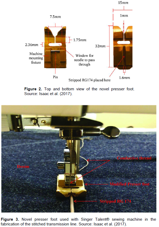
Notwithstanding having a higher signal loss compared to larger diameter cables such as RG58, the RG174 was chosen for its flexibility and smaller diameter which makes it a good candidate for use with the novel presser foot. However, it is important to note here that the presser foot is designed to meet stitching requirements for a stripped RG174 braided coaxial cable only. For a different application say for an RG58 braided coaxial cable, a different presser foot must be designed and necessary adjustments made where necessary to meet its stitching requirements.
SIMULATED AND MEASURED RESULTS
Two sets of measurements were carried out on the stitched transmission line as earlier discussed in this paper. These measurements were carried out at a relative ambient humidity and stable ambient temperature of 23°C to avoid ambient thermal fluctuations.
A lot of components tend to drift slightly even with the best vector network analyser (VNA), due to temperature, humidity, the age of components, etc. Since this has a significant influence on the integrity of the vector analyser measurements, the vector network analyser was calibrated to know the reflection and transmission of the standards to solve for error coefficients. These were achieved by manually entering the properties associated with the calibration kits, and some thru, reflect, line (TRL) calibration kits.
DC resistance
The resistance in any electrical system is by no means constant as it depends on factors like temperature, humidity, the length of wire and high-frequency noise; hence a portion of the electrical energy in an electrical system is always converted to heat energy. This decreases the efficiency of the system and also causes a lot of discomfort to the user. Also, the conductor type plays an important role in determining the DC loss. Hence the comparison between the use of copper wire along with conductive thread and conductive threads only, in fabricating the stitched transmission lines.
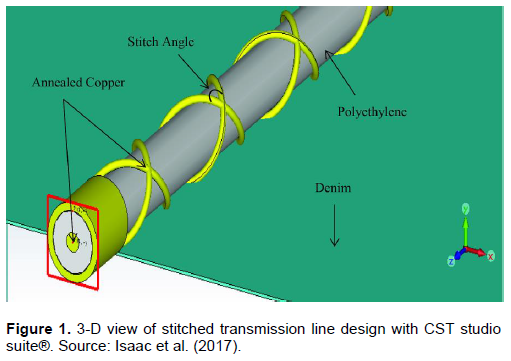
The measured DC resistance of the two stitched transmission lines is as given in Table 4, with results indicating a decrease in DC resistance with the stitched transmission line fabricated with copper wire and conductive thread, and consequently a decrease in DC losses.
Transfer characteristics
The losses associated with the stitched transmission line like every other transmission line are the real loss and mismatch. The real loss is the conductor loss, dielectric loss, and radiation or induction loss, while the mismatch loss is as a result of reflections along the transmission line as it encounters a discontinuity in the characteristic impedance of the line or if the stitched transmission line is not terminated in its characteristic impedance. The radiation loss is more dominant in this case because of the sparsed nature of the shield of the stitched transmission line, which presents the possibility of using the stitched transmission line as a radiating cable or leaky wave antenna. Also, the radiation loss tends to increase with the increase in frequency.
The possibility of also having more of the induction loss along with the dominant radiation loss in the stitched transmission line cannot be ruled out based on its design features. The induction loss occurs when the electromagnetic fields cuts across any conductor and current is being induced in the conductor. When this occurs, power is dissipated in the conductor and this is lost as heat. Additional losses can also be ascribed to the loose connection between the copper wire and conductive threads which could lead to an increase in resistance at the connection.
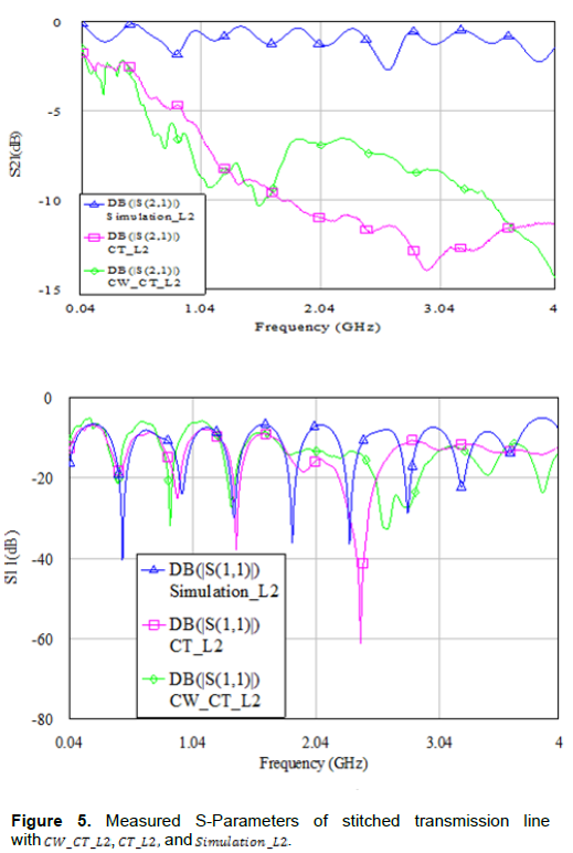
The measured and simulated results of the scattering parameters of the two stitched transmission lines within a frequency range of are presented in Figure 5. Here, refers to the stitched transmission lines constructed with copper wire and conductive thread, with stitch length, stitch width and stitch tension at and respectively, while, refers to the stitched transmission line constructed with conductive threads only, with stitch length, stitch width and stitch tension at and , respectively, and refers to the simulated results with annealed copper wires with stitch length at .
The measured reflection coefficient are below for frequencies up to for and and for and in all of the operation band, respectively, while the transmission coefficients are better than for frequencies up to 2.478 GHz for and for frequencies up to and for frequencies up to , for and , respectively.
The results indicate low DC losses with the stitched transmission line with copper wire and conductive thread, as well as better transmission coefficient. Ripples observed in the stitched transmission line with conductive threads which are as a result of multiple reflections along the line are also seen to be less with the stitch transmission line with copper wire and conductive thread.
A comparison between two stitched transmissions lines constructed with copper wire and conductive thread from Light Stitches® and with conductive threads only has been presented to determine the effect of using copper wires along with conductive threads on its DC loss in an attempt to minimise the DC loss on the stitched transmission line presented by Isaac et al. (2017). Measured DC resistance results obtained from both transmission lines indicates a decrease in DC resistance with the stitched transmission line constructed with copper wire and conductive thread, hence a decrease in DC losses. While scattering parameters results indicate an improved transfer characteristics with fewer ripples on the stitched transmission line constructed with copper wire and conductive thread compared to the stitched transmission line constructed with conductive threads only, slight discrepancies were generally observed between the simulated and measured results which could be attributed to the conductivity of the copper wire and conductive thread used in the first stitched transmission line and conductive threads used in the second, compared to the stitched transmission line modelled as a two wire braided coaxial cable with CST Studio Suite®, and the sparse nature of the shield and uneven geometry of the apertures along the constructed stitched transmission line.
The authors have not declared any conflict of interests.
REFERENCES
|
Choi M, Kim J (2016). Electrical characteristics and signal transmission characteristics of hybrid structure yarns for smart wearable devices. Fibres Polym. 17(12):2055-2061. Chedid M, Belov I, Leisner P (2007). Experimental analysis and modelling of textile transmission line for wearable applications. Int. J. Clothing Sci. Technol. 19(1):59-71.
|
|
|
|
Cottet D, Grzyb J, Kirstein T, Tröster G (2003). Electrical Characterisation of Textile Transmission Lines. IEEE Trans. Adv. Packaging 26(2):182-190.
|
|
|
|
Isaac HD, Flint JA, Seager R (2017). Stitched Transmission Lines for Wearable RF Devices. Microw. Opt. Technol. Lett. 59(5):1048-1052
Crossref
|
|
|
|
Jeon J, Kim S, Koo J, Hong S, Moon Y, Jung S, Kim B (2011). Electrical Characterisation of Differential Stretchable Transmission Line," Microwave Symposium Digest (MTT), 2011 IEEE MTT-S International: pp. 1-4.
|
|
|
|
Kirstein T, Cottet D, Grzyb J, Tröster G (2002). Textiles for signal transmission in wearables. In Proc. ACM of First Workshop on Electronic Textiles (MAMSET 2002), San Jose, CA, USA, 4 October 2002.
|
|
|
|
Leśnikowski J (2011). Textile Transmission Lines in the Modern Textronic Clothes. 89 Fibres Text. Eastern Europe. 19(6):89-93.
|
|
|
|
Leśnikowski J (2015). New Kind of Textile Transmission Line with an Impedance of 50 Ohms. Fibres Text. Eastern Eur. 2(110):51-54.
|
|
|
|
Locher I, Kirstein T, Tröster G (2004). Routing methods adapted to e-textiles, in Proc. 37th International Symposium on Microelectronics (IMAPS 2004).
|
|
|
|
Locher I, Tröster G (2007). Screen-printed textile transmission lines. Text. Res. J. 77(11):837-842.
Crossref
|
|
|
|
Merritt CR, Karaguzel B, Kang T, Wilson JM, Franzon PD, Nagle HT, Pourdeyhimi B, Grant E (2005). Electrical Characterization of Transmission Lines on Specific Nonwoven Textile Substrates. MRS Proceedings. 870. H4.7
View
|
|
|
|
Wait JR (1976). Electromagnetic Theory of the Loosely Braided Coaxial Cable: Part I, IEEE Transaction Microwave Theory Techniques 24(9):547-553.
Crossref
|
|
|
|
Xu Z, Kaufmann T, Fumeaux C (2014). Wearable textile shielded stripline for broadband operation. Microw. Wirel. Compon. Lett. IEEE. 24(8):566-568.
Crossref
|