Full Length Research Paper
ABSTRACT
Explosions due to gas leaks from accidents and human errors are major concerns faced in natural gas and related industries. Understanding its formation and dissociation mechanisms at field conditions is keys to its successful prevention and management. In the present study, two different meshes with different sized flow channels were proposed to prevent and control methane combustion in a circular gas pipeline. The perforated metal steel of 6 mm aperture and woven wire steel mesh with 1.31 mm aperture, 0.28 mm wire diameter installed in between the flange positioned 2000 mm in a 6300 mm horizontal circular pipe were used. The effects of propagated flame flow temperature variation and equivalence ratio on wire gauze combustion have been investigated and analyzed experimentally. Methane-air mixture at variable concentrations within the lower and upper flammability ranges of 6 and 9% were used in creating an explosive mixture through the pipe length. The parameters investigated were measured and recorded. The results indicated that the inflated period for methane-air concentrations and mesh sizes varied significantly with time. The wall temperature decreased with a decrease in mesh size. The woven wire and perforated plate on flame propagation showed greatly the mitigating capability of the meshes, with a flame temperature declining tremendously. Therefore, woven wire and perforated sheets installed in gas pipelines can reduce explosion risks efficiently and effectively. However, woven wire mesh is preferable because it declines the flame temperature compared to the perforated metal mesh.
Key words: Explosion, combustion, flame propagation, temperature, steel meshes (Woven wire and perforated plate).
INTRODUCTION
Natural gas is a hydrocarbon that consists mainly of methane (CH4) but also includes varying amounts of other higher components (Dissanayake et al., 1991; Clayton, 1991; Faramawy et al., 2016). Natural gas has become one of the major sources of energy worldwide due to its cleanest-burning and versatile hydrocarbon, which helps meet the growing energy demand. However, to meet the demand of world energy requirements, the continuous search for it has become of paramount importance. Transporting this commodity in pipes is a common feature of many process industries. However, the process of transporting this flammable gas is safe when the gas contains either no air or air in controlled quantities so that the mixture proportions are always outside the explosive range. An explosion can only occur when these flammable gases or vapor are mixed with sufficient air for the mixture to sustain flame propagation. It is a vastly dangerous commodity, which should be recognized for its hazards and be handled with the proper precautions. Explosions and fires involving explosive gases and vapors compound a significant threat in process industries and other environments where such resources are utilized and handled. Thus, attempts to reduce the risk of gas explosions and fires in these industries continue globally, and much effort and time are required in mitigating accidental gas and vapor cloud explosion (Baker et al., 2012). Additionally, when fuel gas accidentally ignites in conduits, it can result in explosions which, in several instances, cause a transition from deflagration to detonation (DDT), and the behavior depends on the fuel type involved in the explosion (Kundu et al., 2016; Ciccarelli and Dorofeev, 2008; Wang and Wen, 2014; Chen et al., 2017).
The mitigation and prevention of these commodities (Natural gas, CH4) have attracted wide attention by researchers due to their frequent occurrences in the industries (Naito et al., 2011; Yang et al., 2004; Zhang et al., 2014). Many researchers have focused on using ultra-fine water mist in quenching gas explosion (Zhang et al., 2014; Liang and Zeng, 2010; Willauer et al., 2009; Xu et al., 2013). Moreover, researchers had paid more attention in conducting investigations on the mechanism of explosion quenching using various methods and based on the physical and chemical properties; they conclusively yield similar results (Jianhua et al., 2011; Zhou et al., 2018). An experiment conducted by Gelfand et al. (1975) on shock wave propagation in porous media indicated that the solid materials reduce the drag force, decreasing the speed of shock wave propagation in the gas flow pathway.
An explosion is a sudden reaction involving a rapid physical, nuclear, or chemical oxidation reaction or decay, generating an increase in temperature and pressure or both simultaneously. According to Eckhoff (2016), the explosion is an exothermic chemical process that increases a sudden and significant pressure incidence. Simultaneously, a gas explosion is a process where the combustion of a premixed gas cloud, that is, fuel-air or fuel/oxidiser causes a rapid increase of pressure (Bjerketvedt et al., 1997).
Combustion of natural gas is common in domestic appliances such as central heat systems and cooking facilities (El-Mahallawy and Habik, 2002). However, the reaction of fossil fuels, for example, coal or natural gas with air and oxygen releases heat, which has been utilised for different purposes (Eckhoff, 2003). On the other hand, natural gas (methane, CH4) is more advantageous due to its clean nature compared to other fossil fuels because there is no emission of sulphur oxide (SOx) as sulphur is removed from natural gas before combustion (Bjerketvedt et al., 1997). Nevertheless, carbon dioxide, (CO2), carbon monoxides, (CO), and nitrogen oxides (NOx) can be produced by the combustion of natural gas. CO2 emission is intrinsic to the combustion of fossil fuels, which, when reduced, improves the efficiency of the combustion equipment.
There are various ways of fire mitigation, which include the use of foams CO2, and water (Eckhoff, 2016; Zarko et al., 2012; Lees’, 2012), which have significantly indicated promising results over the years, although with limited application depending on the fire source and the surrounding environment. This present study investigates the effect of perforated and wire meshes installed along the flame pathway on flame propagation in a circular pipe. Experiments were conducted with two different sizes of meshes to examine their mitigating extent as the flame propagates through the materials and the flame evolution with both 6 and 9% methane/air mixtures.
EXPERIMENTAL SETUP AND MATERIALS
The schematics of the experimental equipment and configuration used for the test trials are as shown in Figure 1. The experimental test trials were carried out in a horizontal circular pipe divided into two sections by flange connections with 190 mm internal diameter and 6300 mm long. The pipe is made up of two sections: the driver and the transparent section (Plexiglas). The driver section is made of carbon mild steel metal with 2-m long and 8-inch diameter. While the transparent tube section is made up of polymethyl-methacrylate (PMMA)/Plexiglas 4-m long was positioned at middle of the experimental equipment and connected to 0.3-mr long of the same carbon mild steel. These two sections of the tube are then connected with 20-mm flanges at both ends and with the appropriate gasket. The porous stainless-steel meshes were placed at a fixed position in between the flanges at 2000 mm distance. The ignition was affected by electric spark plugs located at the right-hand side of the experimental rig.
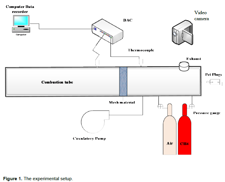
The flame temperature was monitored using K-type thermocouples. Five temperature sensors (K-type thermocouples) were placed at top of the experimental tube at five different locations. Six openings as an exhaust outlet located at the top right-hand of the explosion tube. Gas recirculation system was installed in a parallel recirculation stream to make a pressure differential through the main explosion tube and recirculate accordingly via bypass circuit stream in other to have homogenous fuel gas-air mixture. The Laboratory Methane grade and Industrial grade compressed air in 50 L cylinders with necessary connection including regulators and downstream valves supplied by BOC Company were used for the experiment. GMI Gas-co-seeker was used to verify and ascertain the final gas mixture percentage before igniting in other to maintain safety within the laboratory environment. The high-speed video camera was positioned at 90° at the right-hand side of the experimental apparatus which was used to record/videoing the flame propagation. The Inet-510 expandable modular was used as data acquisition system. It was used because of its compatibility and very simple connectivity to a windows computer for data acquisition. The external measurement devices such thermocouples, pressure sensor thermistors can be connected to Inet-510 wiring box easily. The data sensors (thermocouples and pressure transducers) were then connected to the Inet-510 modular and the modular was connected directly to the computer for data logging.
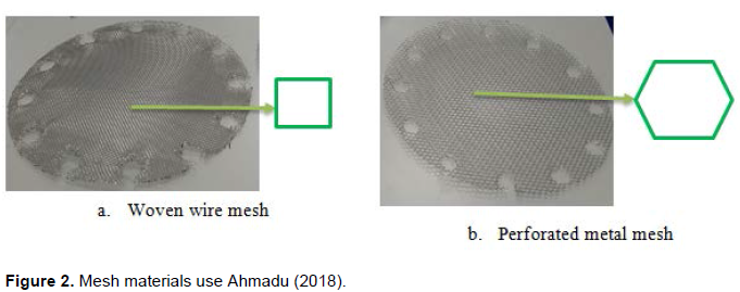
Two different mesh sizes were selected from the range of the meshes suitable in this research study; steel metal mesh was chosen due to its thermal conductivity and its resistance to heat. The perforated steel metal mesh has a hexagonal shape of 6 mm Hex, 6 mm Hole, 500 mm × 500 mm × 0.55 mm while the 304 woven wire stainless-steel mesh perforated with regularly spaced square holes (1.31 mm aperture with 0.28 mm wire diameter). The holes had square edges which were perpendicular to the surface of the sheet as depicted in Figure 2. These meshes were purchased and supplied by mesh company United Kingdom.
Experimental procedures
The experimental equipment was thoroughly cleaned and dried using vocum pump to make it free of any moisture before the run of each trial. The flange at the end of the explosion tube was opened, and the ‘primary key’ was turned onto power and energise the magnetic hinge panel section and manually closed and held in place by the electromagnet. The six-exhaust outlet at the top side of the tube towards the opposite end of the rig were sealed using ‘cling film’ and Velcro straps immediately, after that the gas booster key and air circulation pump were turn on. The gas circulations valves (that is valves D, E, F, and G) were then open. After the circulation pump, the methane supply valve was opened, and then the methane was injected via a calibrated solenoid rotameter at 200 L/min into the combustion chamber. Portable alarm gas detector was used for leakage detection and time was then set and recorded corresponding to each 6 and 9% methane concentration in the chamber using gas-co-seeker.
The data acquisition system and a video camera were switched-on and activated. The mixture (methane/air) was allowed to stabilise for 1 to 2 min to ensure it became quiescent. Before turning on the ‘ignition’ key and subsequent pushing of the ignition button, a verbal description of the configuration was relayed to the video camera, this includes:
(a) The concentration of methane-air mixture
(b) Mesh size inserted
The audible description was used to catalogue video imagery, whereby each file could then be renamed with confidence.
The ignition key was turn-on, and ignition button was pushed to generate a spark and then the mixture was ignited, and explosion developed along the tube length.
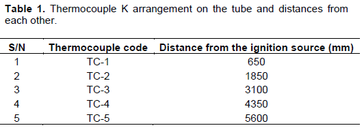
The temperature of the system was captured and recorded along the pipe length from the point of ignition using 5 thermocouple K as described in Table 1.
Several trials were conducted using woven wire mesh and perforated metal sheet obstruction placed at 2000 mm from the ignition source for repeatability and reproducibility.
RESULTS AND DISCUSSION
Free flow temperature profile (No Mesh)
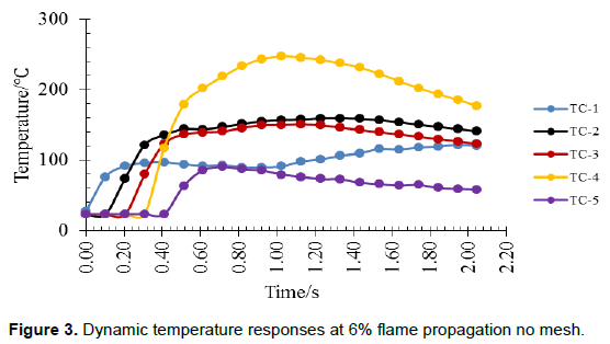
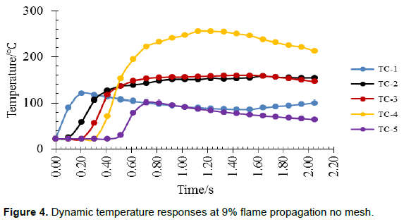
Figures 3and 4 present the thermocouple output data for 6 and 9% methane-air mixtures. As expected, the temperature-time curve displays the ranges of temperature of the flame propagation along the length of the pipe. It was observed from Figure 3that after TC-1 trigger point, there is a rapid increase in the propagated flame temperature from 23.40°C to a maximum flame temperature 247.22°C in thermocouple TC-4 at 1.02 s, which confirmed the exothermic reaction nature of the gas explosion with 6% methane/air mixture. Figure 4exhibits similar flame temperature trends as the mixture concentration was increased to 9%. The TC-4 have maximum flame temperature 256.02°C with the corresponding time of 1.13 s after the trigger point in TC-1. This rapid change between the TC-1 and TC-4 results from lower to upper limit of explosion. However, other thermocouple indicates a lower temperature sequentially compared to thermocouple TC-4 with a further decrease from TC-2 to TC-3, TC-3 to TC-1, and TC-1 to TC-5, respectively. These results of the preliminary experimental trials will be used to compare with subsequent trials dry test with woven wire and perforated metal mesh installed. The following result section shows the set up with 1.31 and 6 mm aperture installed.
Temperature effect on woven wire mesh (1.31 mm)
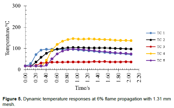
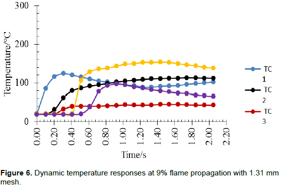
As shown in Figures 5and 6, the temperature variation profile for 6 and 9% methane/air mixtures as the flame propagates through the woven wire mesh. Figure 5shows that the flame temperature increases with time immediately after ignition and cools down to its minimum as the flame escaped the combustion chamber, after which the rate of the temperature decreases from TC4 to TC1, TC1 to TC2, TC2 to TC5 and TC5 to TC3 as the flame propagates further. The TC3 indicates a lower temperature 31.05°C; this is because the T3 thermocouple is next to the mesh. However, as the flame propagated through the mesh, the scattering nature of the flame within the surface hole wall of the mesh divided the flame into various small flaming groups and the rise in intensity of turbulence led to a disturbance in its thermal balance which caused the flame temperature to fall drastically with time. Due to the hole size of the wire mesh, the turbulence after the flame passes through the mesh causing a significant increase in the temperature, due to the heat rejuvenation/accumulation. Figure 6exhibits similar character of a high temperature at thermocouple 4 (TC-4) when the mixture concentration was increased to 9%. It generated a high temperature of about 140°C and rapidly cools down as the flange fall off and the flame escaped the combustion chamber. The mesh is placed immediately before TC-3, the temperature recorded by TC-3 thermocouple shows a lower temperature 32.62°C compared to other temperature sensors placed along the pipe length. This resulted from heat loss by conduction to the mesh which decreases the flame temperature. It is therefore observed that the inflexion point between the equivalent ratios (ER) of 0.61 and 0.95 are in agreement with each other, with 6 and 9% mixture, the time rates of the flame propagation through the mesh were found to be 0.31 and 0.31 s.
Flame propagation behaviour (1.31 mm mesh)
Figures 7and 8 show the photograph of the flame propagation image. Here, with the woven wire mesh in position, as the flame passes through the mesh the flame colour becomes slightly darker and more heterogeneous.
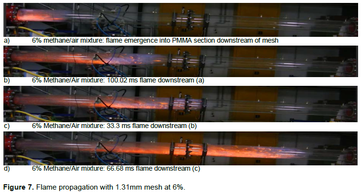
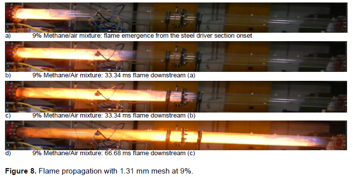
Thus, woven wire mesh and perforated metal sheet were used as a barrier or blockage for flame propagation. Due to the scattering nature of the flame when passing through the mesh which causes the temperature to drastically cool down thereby causing an evolution in the flame front from a strong flame at the start of the ignition to a weak flame as shown Figures 7and 8, respectively.
Perforated metal sheet (6 mm)
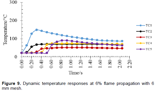
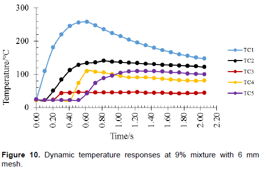
Temperature effect
The temperature variation for 6 and 9% flames with 6 mm perforated metal steel installed. The temperature measured encompasses similar trends as the previous runs presented in Figures 9and 10 but TC-1s recorded the maximum temperature of 148 and 257°C which then declined down as flame propagates further to about 87 and 146°C for 6 and 9% mixtures also reported by Wang and Wen (2014) and Chen et al. (2017). It is observed from Figures 9and 10 that the trends in flame temperature changes with TC-1 having maximum peak flame temperature of 148 and 257°C. This is because when the flame propagates through the perforated mesh, it absorbs heat by conduction rapidly and due to its large specific surface area causes the decrease in the propagated flame energy. Also, it may have resulted from the burning of non-reacted hot mixture that might have escaped the explosion chamber after venting, bear in mind that the exhaust opening is close to the TC1 thermocouple. All other thermocouples indicate a lower temperature sequentially compared to thermocouple TC1 with a further decrease from TC-5 to TC-4 except for the TC3. There was a great drop in flame temperature in TC3 thermocouples to about 45 and 43°C for 6 and 9% mixtures which resulted from the mesh inserted due to its heat convective and conductive nature.
Flame propagation behaviour (6 mm mesh)
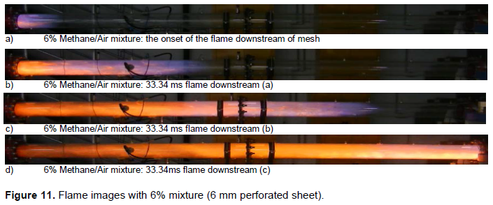
Figure 11presents series of flame propagation video images for 6 and 9 % methane-air mixtures with 6 mm perforated sheet installed. It was observed from Figure 11that after ignition of the mixture, it takes just 20 to 30 ms for the flame to vanished/escaped away from the combustion pipe. These images are as shown in Figures 11and 12. It was observed that the trends of the flame propagation through the perforated metal sheet with 6% mixture shows that the flame colour varies significantly as it propagates along the pipe. At the start of the ignition, an almost stable combustion region appears with two different colours appearing at the same time. Although, the bluish flame head dominates the region, and this shows that more of the methane fuel was burnt completely at the beginning of the explosion. Additionally, it was observed that the flame obstruction due to the perforated metal steel mesh installed, causes flow resistance of the methane-air mixture. This obstruction led to the reduction in the flame front speed and burning rate as it emerges into the transparent tube. A clear separation of the regions appears as the flame propagates further into the transparent tubes, for example, as shown in Figure 11. As the flame continue to propagate, complete and incomplete combustion regions where the two distinct separation regions are observed. The flame front profile formed a cone-like structure as the flame rejuvenates after passing through the obstruction (mesh) and then, the flame colour turns yellow before vanishing from the tube.
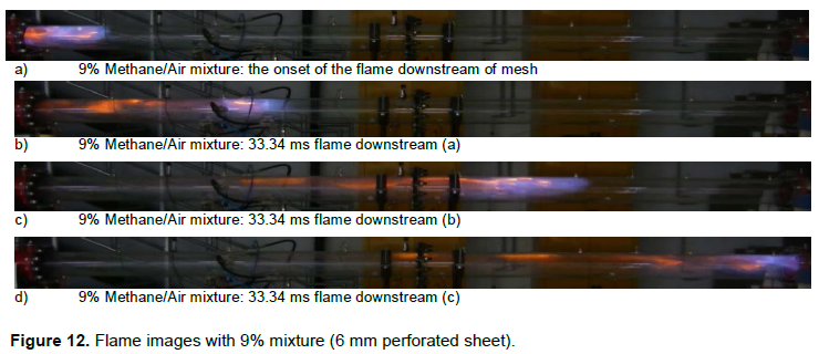
It was observed from Figure 12that the flame appears to be bright from the onset with traces of light yellow at the middle with the top of the flame (flame front) being blue. The flame appears in a cone-like shape with a wavy like flame front. This behaviour indicates incomplete combustion occurred as the flame hits the mesh and methane fuel was burnt completely at the tip of the flame. Additionally, it was observed that the flame obstruction due to the perforated mesh installed, causes flow resistance of the methane-air mixture. This obstruction led to the reduction in the flame front speed and burning rate as it emerges into the transparent tube. As the flame continue to propagate, the flame front turned into a cone-like shape with the blueish colour at the tip of the flame front. However, the flame front remains blue until the end of combustion where the end flange had fallen off, and the flame diffuses into the surrounding.
Comparative analysis between wire mesh, perforated plates, and no mesh on flame mitigation
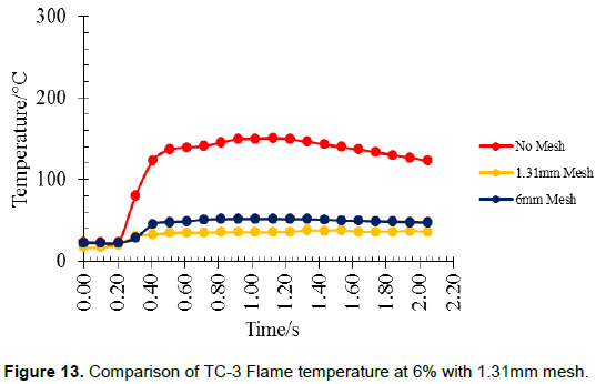
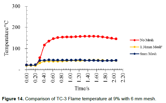
Figures 13and 14 show comparatively the TC-3’s flame temperature differences between woven wire, perforated plate, and no mesh (free flow). In the case of no mesh, the maximum flame temperature observed was 149.37°C, while the woven wire and perforated plate recorded the maximum flame temperature 35.49 and 51.65°C, respectively, at the corresponding times 0.92 s for 6% mixtures. And for the 9% mixtures, the maximum temperature observed in no mesh scenario was 155.37°C, while for both mesh scenarios, the maximum temperature is 42.13 and 44.96°C at the same time, of 0.92 s. These increases in maximum temperatures in both mixture scenario can be attributed to the higher heating values of the higher mixture and thus higher equivalence ratio. The peak flame temperature for the three scenarios was observed at 0.41 s to be 123.02, 32.04 and 45.33°C for 6% mixtures. While for 9% mixtures, the peak flame temperatures are 116.38, 39.87 and 44.60°C at the same time of 0.41 s. These indications showed that when the explosion flame propagates through the tiny holes or structure of the woven wire mesh, the flame is divided into several smaller flames, which caused the flame front to be discontinuous, and the heat of the reaction exchanges with the woven wire mesh openings/material wall surface and vice versa. Moreover, the ability of the mesh materials (woven wire and perforated plate) to attenuate the temperature of the explosion flame increases with a decrease in the opening size, and the fire resistance increases with the decrease in the thickness.
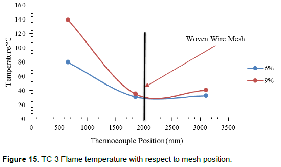
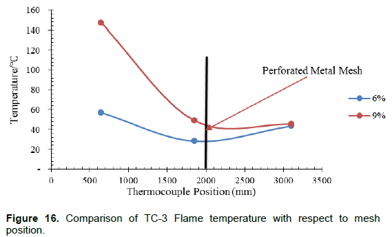
Figures 15and 16 present the flame temperatures from the triggered point along the pipe length with respect to Meshes position. These further showed the relationship between the flame temperature and thermocouple distance from the flame triggered point with respect to the effect of the meshes (woven/perforated) utilized in this study. It is observed that at the start of the ignition, the flame temperature increases rapidly to 79.62 and 139.22°C at 6% mixture and 57.01C and 147.15°C at 9% mixtures at the same distance of 650 mm. These huge differences in the flame temperatures might have resulted from the weak lean combustion and high lean combustion mixtures. As the flame propagated to the meshes positions, the flame temperature drastically falls to 31.05 and 35.05°C at 6% and 43.57C and 45.25°C at 9% mixtures at 2000 mm. These drastic falls in flame temperature clearly showed the mitigating effect of both meshes installed along the pipe length. However, Figure 15clearly shows more mitigating effects of quenching when compared with Figure 16.
CONCLUSION
Generally, the results obtained from the experiment clearly indicates that both woven wire and perforated metal mesh within the circular pipeline drastically reduce the flame's temperature and deteriorate the energy of the flame and can be used as an explosion mitigant. However, the insertion of woven wire mesh and perforated metal mesh significantly hinders flame propagation temperature. Thus, when the meshes are placed at the different intervals within the pipeline will reduce the level at which the flame propagates or extinguishes/mitigates the flame.
Moreover, the absorbing sound ability of the woven wire mesh was better than the perforated metal mesh, thus, both have a suitable flame temperature decaying rate and great fire/flame suppression effects.
CONFLICT OF INTERESTS
The authors have not declared any conflict of interests.
REFERENCES
|
Ahmadu AA (2018). Flame propagation through different sizes of metal mesh and mitigation using fine water sprays, University of Salford. |
|
|
Baker WE, Cox PA, Kulesz JJ, Strehlow RA, Westine PS (2012). Explosion hazards and evaluation. Elsevier. |
|
|
Bjerketvedt D, Bakke JR, Van Wingerden K (1997). Gas explosion handbook. Journal of Hazardous Materials 52(1):1-150. |
|
|
Chen P, Huang F, Sun Y, Chen X (2017). Effects of metal foam meshes on premixed methane-air flame propagation in the closed duct," Journal of Loss Prevention in the Process Industries 47:22-28 |
|
|
Ciccarelli G, Dorofeev S (2008). Flame acceleration and transition to detonation in ducts. Progress in Energy and Combustion Science 34(4):499-550. |
|
|
Clayton C (1991). Carbon isotope fractionation during natural gas generation from kerogen. Marine and Petroleum Geology 8(2):232-240. |
|
|
Dissanayake D, Rosynek MP, Kharas KCC, Lunsford JH (1991). Partial oxidation of methane to carbon monoxide and hydrogen over a Ni/Al2O3 catalyst. Journal of Catalysis 132(1):117-127, |
|
|
Eckhoff RK (2003). Dust explosions in the process industries: identification, assessment and control of dust hazards. Elsevier, |
|
|
Eckhoff RK (2016). Explosion hazards in the process industries. Gulf Professional Publishing. |
|
|
El-Mahallawy F, Habik SD (2002). Fundamentals and technology of combustion. Elsevier. |
|
|
Faramawy S, Zaki T, Sakr AE (2016). Natural gas origin, composition, and processing: A review. Journal of Natural Gas Science & Engineering 34:34-54. |
|
|
GelFand BE, Gubin SA, Kogarko SM, Popov OE (1975). Investigation of the special characteristics of the propagation and reflection of pressure waves in a porous medium. Journal of Applied Mechanics and Technical Physics 16(6):897-900, |
|
|
Jianhua S, Yi Z, Chunrong W, Shang X, Donghui H (2011). "The comparative experimental study of the porous materials suppressing the gas explosion. Procedia Engineering 26:954-960, |
|
|
Kundu S, Zanganeh J, Moghtaderi B (2016). A review on understanding explosions from methane-air mixture. Journal of Loss Prevention in the Process Industries 40:507-523. |
|
|
Lees F (2012). Lees' Loss prevention in the process industries: Hazard identification, assessment and control. Butterworth-Heinemann, |
|
|
Liang Y, Zeng W (2010). "Numerical study of the effect of water addition on gas explosion," Journal of Hazardous Materials 174(1-3):386-392. |
|
|
Naito H, Uendo T, Saso Y, Kotani Y, Yoshida A (2011). "Effect of fine water droplets on extinguishment of diffusion flame stabilized in the forward stagnation region of a porous cylinder," Proceedings of the Combustion Institute 33(2):2563-2571. |
|
|
Wang CJ, Wen JX (2014). "The effect of a perforated plate on the propagation of laminar hydrogen flames in a channel-a numerical study," International Journal of Hydrogen Energy 39(36):21335-21342. |
|
|
Willauer HD, Ananth R, Farley JP, Williams FW (2009). "Mitigation of TNT and Destex explosion effects using water mist," Journal of Hazardous Materials 165(1-3):1068-1073. |
|
|
Xu H, Li Y, Zhu P, Wang X, Zhang H (2013). "Experimental study on the mitigation via an ultra-fine water mist of methane/coal dust mixture explosions in the presence of obstacles," Journal of Loss Prevention in the Process Industries 26(4):815-820. |
|
|
Yang W, Parker T, Ladouceur HD, Kee RJ (2004). "The interaction of thermal radiation and water mist in fire suppression," Fire Safety Journal 39(1):41-66. |
|
|
Zarko VE, Weiser V, Eisenreich N, Vasil'ev AA (2012). Prevention of hazardous fires and explosions: The transfer to civil applications of military experiences, vol. 26. Springer Science & Business Media. |
|
|
Zhang P, Zhou Y, Cao X, Gao X, Bi M (2014) "Enhancement effects of methane/air explosion caused by water spraying in a sealed vessel," Journal of Loss Prevention in the Process Industries 29:313-318. |
|
|
Zhou C, Mu X, Zhang Y, Wang X (2018). "Review on the research methods of the barrier and explosion-proof properties of porous materials. AIP Conference Proceedings 1995(1):20003. |
|
Copyright © 2024 Author(s) retain the copyright of this article.
This article is published under the terms of the Creative Commons Attribution License 4.0


