Full Length Research Paper

ABSTRACT
INTRODUCTION
Infill drilling and fracturing technology is considered to be an effective method to enhance low permeability oil field.
Before 1960, ultimate recovery was supposed to be unrelated to well spacing (Ching et at., 1989). In 1980, Van Everdingen and Kriss (1980) stated that infill drilling could be adopted in enhanced oil recovery (EOR), however their study was not convincing enough due to inadequate data. Barber and George (1983) published case studies from Texas, Oklahoma and Illinois, proving that infill drilling could increase oil production in combination with well pattern adjustments. In one example presented by these authors, wells’ pattern has changed from a peripheral pattern to an inverted nine-spot with infill wells accounting for 68% of the overall daily production. In 1989, Ching et al. (1989) made the general statement that infill drilling in carbonate reservoirs can noticeably increase production during water flooding. Hydraulic fractures are usually assumed to propagate along the maximum stress direction with consequent impact on well pattern design. Hidayati et al. (2001) and Schutjens and Kuvshinov (2010) thought that the injection or production of large volumes of fluid into or from a reservoir can significantly change the effective in situ stress distribution, which could deviate hydraulic fractures from its forecasted path. The magnitude of reorientation depends on pressure gradients and thus, it is controlled by injection/production rates and pore pressure variations in the reservoir (Zhai and Sharma, 2007). The radius of fracture reorientation has been investigated by analytical and experimental methods (Deimbacher et al., 1993; Rod 2005). Besides vertical drilling, studies about stress reorientation around horizontal wellbores were also conducted (Hidayati et al., 2001; Singh et al., 2008; Sharma et al., 2008).
As for the probability of fracture reorientation, Wright (1995) found that water flood related to secondary recovery in Diatomite reservoirs have caused directions of infill hydraulic fractures to rotate with more than 60° away from the original direction. Weijers (1999) studied the fracture reorientation in steam injection wells and proposed that the induced fractures grew predominantly along the direction that was 45° off of the preferred fracture plane in South Belridge, Lost Hills, and Cymric fields. Other studies also showed that the azimuth of reoriented fractures is usually between 0° and 90° (Wright, 1994; Wolhart, 2007).
Roussel et al. (2013) used a numerical model of fracture propagation from an infill horizontal well drilled within stress field affected by prior production from offset wells to simulate the occurrence of stress reversal within the infill region and demonstrated its impact on the direction of fractures propagated from an infill well. A window of opportunity has been proposed to improve the stimulation efficiency by fracturing the infill well around (ideally slightly before) the time when principal horizontal stresses change directions. They also suggested considering the risk of stress reversal before infill operations. In the Ansai low permeability reservoir, the EOR development hinges on infilling vertical well stimulation.
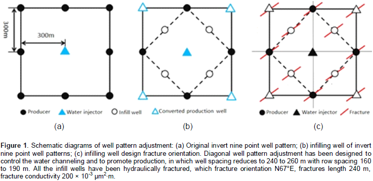
The primary well pattern in the pilot area was inverted square nine-spot, whose well space is 300 × 300m (Figure 1a). After more than 20 years of water injection, well pattern designed for primary recovery are no longer efficient. Water cut of vertical wells increases rapidly and the production rate decreases accordingly. To enhance efficiency of water flooding, the pilot test well pattern adjustments including converting, infilling and hydraulic fracturing have been adopted (Figure 1b and c).
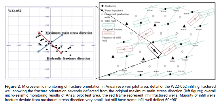
Even though well infilling and hydraulic fracturing in pilot area significantly increased the well group production, some problems still exist. Twenty-four (24) infill wells were put into production after fracturing in the first stage, and early water breakthrough happened in most of new infill wells. About 80% wells seriously flooded after a short time production, reaching 90% water cut at the beginning of development. Since the fracture treatment was not optimized in advance, the fracture parameters for infill wells in the pilot area are proved to be unsuitable. Meanwhile, micro-seismic monitoring indicates that hydraulic fractures of infill wells do not always extend along the maximum stress direction, implying reorientation of the infill wells’ fractures (Figure 2). One of the most striking differences between W22-052 and any other infilling wells is fractures’ orientation and fractures’ length. However, evaluation of the fracture direction was not very insightful due to the diverse stress variations from region to region at each infilling well.
EXPERIMENTAL DESIGN
Infill well drainage patterns
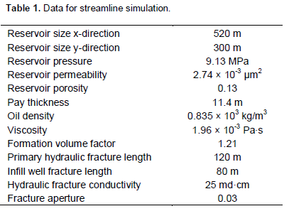
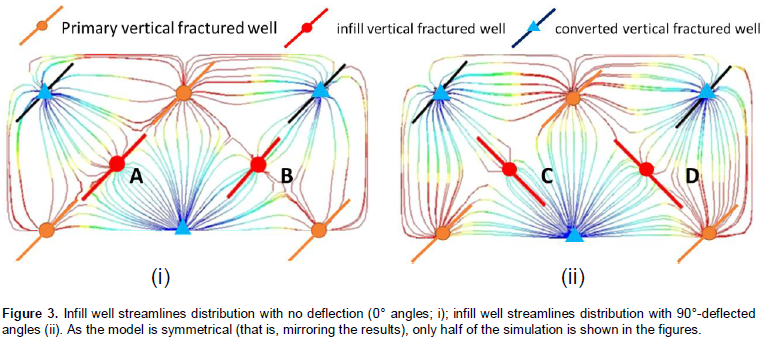
Reservoir simulation model for Ansai oil field was built and calibrated by history matching. To further understand the drainage patterns and flow behaviors of infill well with different fracture orientations in inverted nine-spot well pattern, series of streamline three-dimensional theoretical model were conducted by using local grid refinement method (LGR). Two cases are considered respectively: firstly, no infill well fracture reorientation happens, in other words, all well fractures remained consistent; next is the infill fractures deflection at 90°. Models are calibrated using properties of the Ansai low permeability oil reservoir (Table 1).
As shown in Figure 3, streamline distributions between injection and production wells are not evenly, and infill fracture orientation could significantly affect fluid flow behavior. When the infill fracture orientation is perpendicular to the production-injection connection line, the waterlines distributed uniformly on both sides of infill Well A (Figure 3i). However, due to the fracture deflection, the streamline becomes denser at the tip of the injector well fractures, which could enhance the sweep efficiency around the Well D (Figure 3ii). In these two cases, as long as the infill fracture orientation along with the injection wells or inject waterline, the water-cut of the production well increases significantly. For example, Well B production is more sensitive to the fracture reorientation, which increases the reservoir heterogeneity in small region.
Fracture reorientation is a complex phenomenon during hydraulic fracture stimulation. Principal stress direction may change due to the pore-elastic effects (Hagemann et al., 2012) and water injections (Perapon et al., 2012). In this paper, series reservoir simulation models were conducted to address the Minimum-risk Optimization (MRO) of infill fractures when fractures orientation cannot be pre-determined. With further investigation of drainage patterns between Wells A and B, we find that the relative location relationship between infilling wells and injector wells affects the optimal infill fracture designs. For example, Wells A and B should be treated separately during the hydraulic fractures design, which may have different optimal fracture properties.
RESULTS AND DISCUSSION
Infill well fracture half-length optimization
Cases without fracture-reorientation
Simulation models were conducted to find the optimal length of infill fractures. The models’ fractures have no deflection at any angles (that is, no deflection, fractures parallel to the original direction of maximum principal stress N67°E). Figure 4 shows the results of optimal fracture length of infill wells at different locations. Well A is expected to have longer fracture half-length, the cumulative production oil improve with the increase of the fracture length. As fracture length increases around 70 m, the growth of cumulative production curve dives into the lower level. For well B, on the contrary, the maximum of cumulative production can be achieved when fracture half-length reach around 50 m.
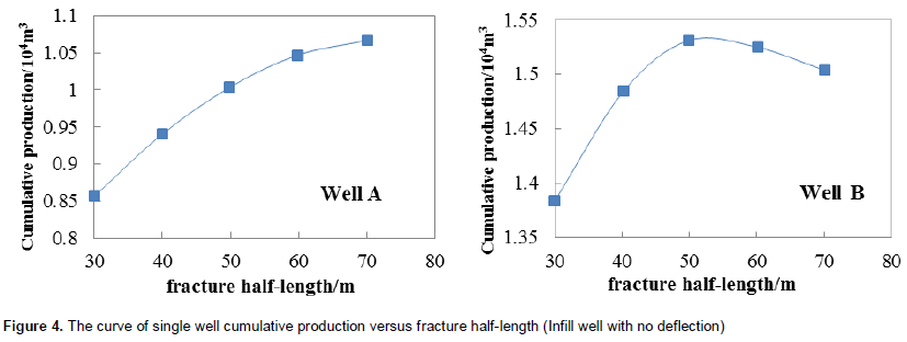
This confirms that the optimal value of infill fracture parameter is totally different in case of infill locations. In addition, the optimal result for infill Wells A and B can be affected by other factors, which primary fracture length and well space should be considered.
Cases with fracture reorientation
Assuming that infill fractures could reorient with arbitrary angle, in this case, 10 reservoir simulation models have been conducted to address the problem of optimal fracture length design with fracture reorientation. The original maximum stress direction (N67°E) was set as the initial value, which is zero rotation angle (θ = 0) (as shown in Figure 5). Infill fractures deflect in the circle to cover different areas, which anticlockwise the rotation angle increases. Otherwise, the angle decreases when the rotation is clockwise. Table 2 proposes the simulation schemes of different fracture deflection angles.
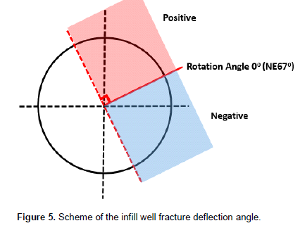
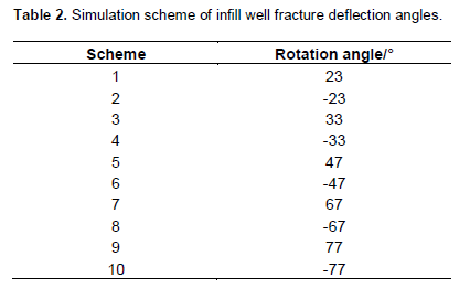
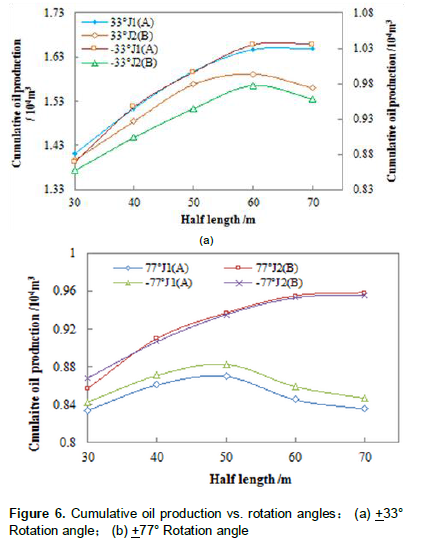
Figure 6 shows that the smaller deflection angles of the infill fracture can achieve, the more cumulative production. After 15 years’ production, infill Well A at the angle ±33° always produced 30% more oil than at the rotation angle ±77°, which means that the smaller fractures’ reorientation has benefit for ultimate reservoir recovery. Infill wells at different locations relative to injection wells have different optimal fracture length. For example, the optimal infill fracture length of Well B ranges from 50 to 60 m, which is smaller than Well A.
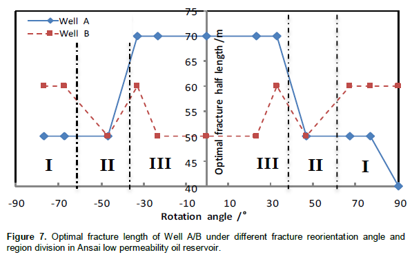
The summary of the optimal value of infill fractures with respect to the rotation angles is proposed in Figure 7. The solid line and the dashed line represent the optimal fracture half-length of Wells A and B with different relative locations, respectively. The optimal values of each well are symmetric about the maximum principle stress direction (θ = 0°). The entire range of angles can be divided into three regions: I, II and III.
In Region I, the optimal fracture half-length of Well B is longer than Well A. The optimal values keep constant with varying deflection angles in Region II; and in Region III, the relation between optimal infill fracture length of Wells A and B is opposite to that in Region I. The significant difference in the hydraulic fracture’s length between Wells A and B is evident from simulation results and flow behavior, which is highly depended on infill fracture reorientation and the location of injection. However, the future fracture reorientation angles of infill wells are difficult to determine precisely in case of complex stress distribution in oil field with fractured well patterns especially after long-time production. If the infill fracture could not be optimized based on precise measurement of stress distribution, which is difficult to get actually, the water channeling would happen and lower the water flooding recovery. Obviously, it is meaningful to present MRO of infill fractures considering the balance between maximum production and safety risks.
Fracturing safety interval (FSI)
As previously mentioned, the understanding of infill well fracture propagation could be improved through the application of micro-seismic results as shown in Figure 2 into reservoir simulation analysis. Because most of micro-seismic results of infill wells (about 90%) as shown in Figure 2 show a rather small deflection angle between 0 and 60°, which means that greater probability of fracture reorientation are mostly likely to happen in Regions II and III (Figure 7). In this study, the weighting average method is employed to calculate the range of favorable fracture half-lengths considering the balance between maximum production and minmum risks due to fracture reorientation (Equation 1), which can also be called FSI.

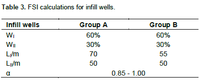
In Equation 1, FSI is the range of the favorable fracture half-lengths, WI is the weight coefficient of Region I (percentage) and WII is the weight coefficient of Region II (percentage), which is determined by the proportions of fracture reorientation in Regions I and II according to the statistics data of micro-seismic monitoring results (Figure 2). α is the safety factor, which we suggest to be ranged from 0.85 to 1.05 depending on the monitoring results of existing wells near infill well groups in study. The smaller the angle (0~90°) between the fracture orientation and production-injection connection line in the neighborhood well groups, the smaller this safety factor would be. LI, LII, the theoretically optimal fracture half-length depends on the values of different regions in Figure 7, for example, if fracture deflection angle in the neighborhood well groups was monitored to be larger than 60°, the recommended infill fracture half-length of well groups in study are around 60 m for both Group A wells B. So according to the fracture micro-seismic monitor data in the Ansai reservoir and simulation results discussed above, the approximate value of WI, WII, LI, LII can be assumed as shown in Table 3.
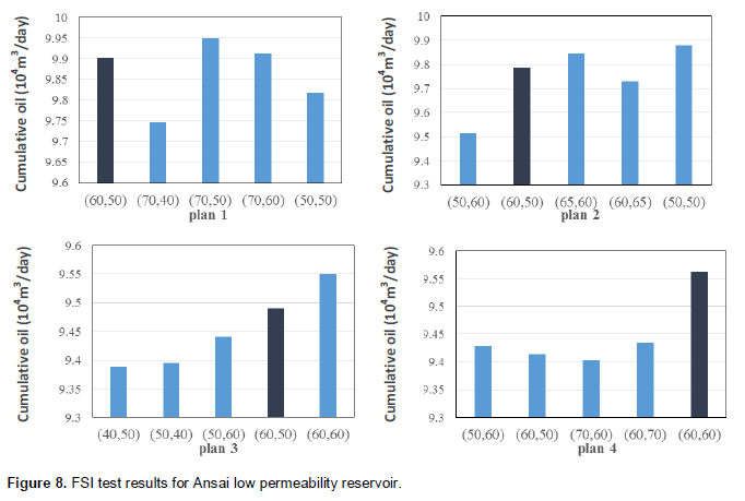
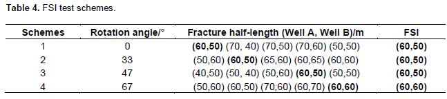
Thus, the FSI for Group A ranges from 54 to 64 m, and Group B ranges from 45 to 56 m. To test the result of well performance at the favorable fracture half-length determined by FSI, the favorable fracture half-length can be chosen for Group A (60 m) and Group B (50 m) which fracture deflection angle is 0°, 33° and 47°. As the fracture deflects to 67°, the optimal fracture half-length is same, which is both 60 m. The cumulative oil production result shows that under different fracture directions, well groups with favorable fracture half-lengths can always achieve a relatively good cumulative oil production (Figure 8). This proves that even if it is hard to determine the infill well fracture orientation, the fracture half-length still could be chosen from FSI (Table 4).
CONCLUSIONS
This study proposed one optimization approach for the fracturing design of infill wells in existing reverse nine-spot well patterns and its application in Ansai oilfield, CHN.
1) Infill well performance and micro-seismic monitoring results both show that the probability of fracture reorientation increase due to long-time production of existing well pattern. Some infill wells fractures show adverse orientation, consequently causing serious consequences such as early water breakthrough, and even burst water floods, as happened to production wells in the pilot test.
2) Base on the well performance, infill wells in inverted nine-point pattern can be subdivided into two categories depending on their locations relative to existing injection wells. Wells of each group type have different optimal fracture half-lengths. However, they share one same optimal half-length within one same group.
3) According to the optimal fracture half-length under different fracture deflection conditions, three characteristics angle region have been identified. In Region I, the favorable fractures length of Well Group A should be larger that of Well Group B, and the opposite in region III, the approximately same in Region II.
4) Based on the difficulty of precise measurement of stress distribution after long-production in reservoirs, and the possible water channeling would happen after infill well fracturing. The MRO method and FSI are applicable to optimal design of infill fractures considering the balance between maximum production and uncertain safety risks.
CONFLICT OF INTEREST
The author(s) have not declared any conflict of interest.
ACKNOWLEDGEMENTS
This paper was supported by Program for Changjiang Scholars and Innovative Research Team in University, PCSIRT (IRT1294); National Basic Research Program of China (2014CB239103), and The Fundamental Research Funds for the Central Universities (13CX06030A).
REFERENCES
|
Barber AH, George CJ, Stiles LH, Thompson BB (1983). Infill drilling to increase reserves-actual experience in nine fields in Texas, Oklahoma, and Illinois. SPE JPT. 35(08):1530-38.
|
|
|
|
|
|
|
|
|
|
|
|
Deimbacher FX, Economides MJ, Jensen OK (1993). Generalized performance of hydraulic fractures with complex geometry intersecting horizontal wells. SPE Paper 25505 presented at the Production Operations Symposium held in Oklahoma City, Oklahoma. U.S.A. March 21-23.
|
|
|
|
|
|
|
|
|
|
|
|
Roussel NP, Horacio F, Adolfo AR (2013). Hydraulic fracture propagation from infill horizontal wells. SPE Paper 1666503 presented at SPE Annual Technical Conference and Exhibition, 30 September-2 October, New Orleans, Louisiana, USA.
|
|
|
|
|
|
|
|
|
|
|
|
Rod HM (2005). Injection fracturing in a densely spaced line drive waterflood - The Halfdan Example." SPE Paper 94049 presented at the 2005 SPE Europe/EAGE Annual Conference held in Madrid, Spain, June 13-16. Sharma A, Chen HY, Teufel LW (2008). Flow-induced stress distribution in a multi-well reservoir." SPE Paper 39914 presented at the 2008 Rocky Mountain Regional/Low Permeability Reservoirs Symposium and Exhibition held in Denver, Colorado, U.S.A, April 5-8.
|
|
|
|
|
|
|
|
|
|
|
|
Singh V, Roussel NP, Sharma MM (2008). Stress reorientation and fracture treatments in horizontal wells. SPE Paper 116092 presented at the SPE Annual Technical Conference and Exhibition, Denver, Colorado, USA, September 21-24.
|
|
|
|
|
|
Weijers L, Wright CA, Demetrius SL (1999). Fracture growth and reorientation in steam injection wells. SPE Paper 54079 presented at the 1999 SPE International Thermal Operations/Heavy Oil Symposium, Bakersfield, California, March 17-19.
|
|
|
|
|
|
Wright CA (1994). Reorientation of propped re-fracture treatments in the Lost Hills Field.SPE Paper 27896 at the 1994 SPE Western Regional Meeting, Long Beach, California, March 23-25.
|
|
|
|
|
|
Wright CA, Conant RA (1995). Hydraulic fracture reorientation in primary and secondary recovery from low-permeability reservoirs. SPE Paper 30484 at the SPE Annual Technical Conference and Exhibition, Dallas, Texas, October 22-25.
|
|
|
|
|
|
Wolhart SL, McIntosh GE, Zoll MB, Weijers L (2007). Surface tiltmeter mapping shows hydraulic fracture reorientation in the Codell Formation. SPE Paper 110034 at the SPE Annual Technical Conference and Exhibition, Anaheim, California, U.S.A. November, 11-14.
|
|
|
|
|
|
Zhai ZY, Sharma MM (2007). Estimating fracture reorientation due to Long Term Fluid injection/production." SPE Paper 106387 presented at the 2007 SPE Production and Operations Symposium held in Oklahoma City, Oklahoma, U.S.A, March 31- April 3.
|
|
Copyright © 2024 Author(s) retain the copyright of this article.
This article is published under the terms of the Creative Commons Attribution License 4.0


