ABSTRACT
Induction motors are currently used in many industrial applications. Thus, their control techniques have received a lot of interest. An efficient method of induction motor control is the Direct Torque Control (DTC). It is considered particularly interesting since it is independent of machine rotor parameters and requires no speed or position sensors. This paper presents a simulation of a DTC strategy for three-phase induction motors based on the Field Programmable Gate Array (FPGA) technology. The real controller is not experimentally tested. A specific methodology for the hardware description language in VHSIC Hardware Description Language (VHDL) is presented. This paper summarizes the prior work before implementing the experimental FPGA control of an induction motor. This methodology allows one to verify the behavior of the VHDL codes before their implementation, reducing the risks of significant changes when implemented. The VHDL design technique for DTC-based speed control is designed through the descriptions of coordinate transformation, speed controller, stator flux and torque estimator, stator flux and torque controller, and stator flux position detector. The simulation is performed using the MATLAB/Simulink, DSP Builder, and Quartus II software, on an Altera DE2-115 board. Simulation results verify the validity of the proposed method.
Key words: Digital control, induction motor, digital signal processing, VHSIC Hardware Description Language (VHDL).
The direct torque control (DTC) techniques of three-phase induction motors has gained popularity in industrial applications mainly due to its simple control structure. Most researchers have focused on DTC strategies using Microprocessors or Digital Signal Processors (DSPs). However, with Field Programmable Gate Arrays (FPGAs), the whole DTC can be implemented using only one chip (Karimi et al., 2007).
The VHSIC Hardware Description Language (VHDL)
has often been used for implementing digital applications. The VHDL is a hardware description language for describing digital designs. The VHDL simplifies the development of complex systems, such as DTC because it is possible to simulate a digital system from a high-level of abstraction (Perry, 2004).
Traditional software-based simulation has the disadvantage of being unable to exactly replicate real operating conditions. Testing digital control systems for electric drives and power electronics applications can be costly and time-consuming (Niu et al., 2016; Casadei et al., 2013; Matic and Vukosavic, 2011; Pandya and Chatterjee, 2010).
Pereira et al. (2015) proposed a virtual teaching platform of DTC for induction motors to assist in the education of undergraduate students. This solution increases the realism of the simulation while eliminating the risk of damaging the actual drive or plant.
The study of DTC control strategies in three-phase induction motors has attracted significant interest by researchers. Ibrahim et al. (2015) presented a new proposal to drive DTC using a fuzzy controller, and their simulated results showed great potential for this strategy. Recently, many papers have been published on real-time simulations used for the design and testing of electric drives and power electronic systems (Soufien et al., 2015). For mapping the design on reconfigurable architecture, such as FPGA, several authors have previously presented interesting design methodologies (Sandre-Hernandez et al., 2016; Barlas et al., 2010; Da Costa et al., 2014).
The contribution of this work is the development of a digital controller with a DTC algorithm applied to a three- phase induction motor using VHDL. The real controller is not experimentally tested. The simulation results of the implemented DTC algorithm were evaluated through comparison to previously designed and tested MATLAB/Simulink simulations.
This paper is organized as follows. First is a brief description of the three-phase induction motor. Next is a presentation of the mathematical model of the induction motor, followed by a brief description of the voltage source inverter. Thereafter, the principle of the DTC was described, and the software simulation platform along with the DTC strategy simulation was presented. The test simulation results was presented and the study concluded.
THREE-PHASE INDUCTION MOTOR
The behavior of three-phase induction motors is usually described by their voltage and current equations. The coefficients of the differential equations that describe their behavior are time-varying (except when the rotor is stationary). The mathematical modeling of such a system tends to be complex since the flow linkages, induced voltages, and currents change continuously as the electric circuit is in relative motion. For the analysis of such a complex electrical machine, mathematical transformations are often used to decouple variables and to solve equations involving time-varying quantities by referring all variables to a common frame of reference (Casadei et al., 2013; Sandre-Hernandez et al., 2016). Among the various transformation methods available, the well-known methods include the Clarke transformation and Park transformation.
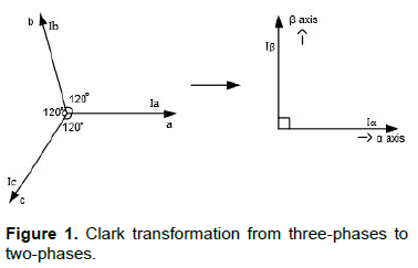
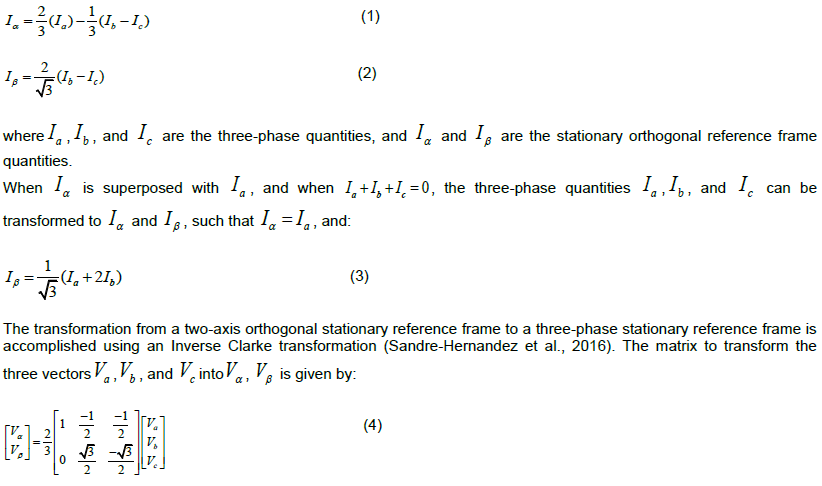
The Clarke transformation converts balanced three-phase quantities ( ) into balanced two-phase quadrature quantities ( ). The Park transformation converts vectors in a balanced two-phase orthogonal stationary system into an orthogonal rotating reference frame (d, q). Both the Clarke and Park transformations are mainly used in vector control architectures related to permanent magnet synchronous machines and asynchronous machines, respectively (Sandre-Hernandez et al, 2016). The three-phase quantities are translated from the three-phase reference frame to the two-axis orthogonal stationary reference frame using the Clarke transformation, as shown in Figure 1. Equations 1 and 2 express the Clarke transformation.
MATHEMATICAL MODEL OF THE INDUCTION MOTOR
The magnitudes involved in the fundamental expressions of the motor voltage are related both to the reference of the stator and to the reference of the rotor.
Thus, it is necessary to obtain a single and common reference for the stator and rotor. As the DTC technique controls stator quantities, such as currents, voltages, and flow, to facilitate the mathematical modeling of the MIT, we adopted the stationary reference. All the values evaluated are based on the mathematical model of the motor in a steady-state condition.
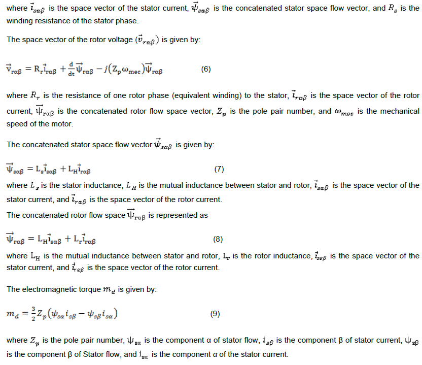
where is the pole pair number, is the component α of stator flow, is the component β of stator current, is the component β of Stator flow, and is the component α of the stator current.
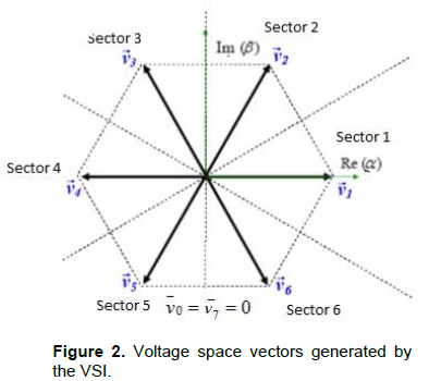
The topology of a Voltage Source Inverter (VSI) is comprised of six Insulated Gate Bipolar Transistors (IGBTs) and six freewheeling diodes (Sandre-Hernandez et al., 2016). Assuming that in every instant the switching devices can accept only one of the two possible states, namely on (1) or off (0), the VSI has only eight possible switching states, generating six active-voltage space vectors (AVSVs) and two zero-voltage space vectors (ZVSVs) . Using the Clarke transformation of Equation (7), the states of the inverter can be mapped onto the α-β complex plane which are shown in Figure 2.
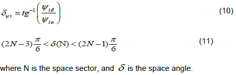
The space sector N is obtained from the angle between the stationary reference and the stator flow (Equation (10)), and is limited by Equation (11):
PRINCIPLE OF DIRECT TORQUE CONTROL
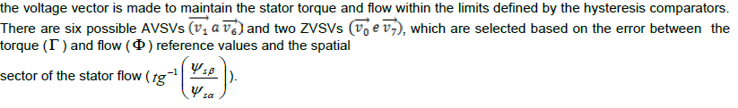
A summary block diagram of the DTC technique is presented in Figure 3 using hysteresis comparators, a motor estimation model, and switching logic. The main objective of this technique is to control the torque and the flow of the stator using the comparators, ensuring a fast torque response. The vector table is used to select the voltage vector to be applied to the stator, determined by the switches that must be activated in the inverter (space modulation). The choice of the voltage vector is made to maintain the stator torque and flow within the limits defined by the hysteresis comparators.
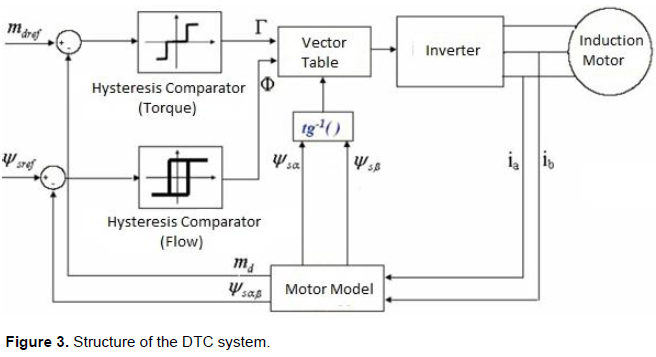
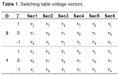
The currents measured at the motor input ( ) are inputs from the “motor model” block, which estimates the torque and the stator flow at that instant, in addition to the space sector where the stator flow is located. The estimated stator torque ( ) and flow ( ) are compared to their respective references ( ). Comparison errors are inputs from the hysteresis comparators (usually two-levels for the flow and three-levels for the torque), which verify that the torque and flow are within their given limits. The outputs of these comparators ( and ), as well as the stator flow space sector, are inputs from the “Vector Table,” which determines the proper switching of the inverter to maintain the stator flow and torque close to its reference values. Table 1 presents the table of voltage vectors to be applied to the inverter.
SIMULATION PLATAFORM SOFTWARE
The simulation platform consists of two software programs: MATLAB/Simulink and DSP Builder. MATLAB/Simulink is responsible for simulating the power part of the drive and control, whereas the DSP Builder software converts the MATLAB/Simulink codes to the VHDL language and allows the loading of the codes into the FPGA device (Da Costa et al., 2014; Karimi et al., 2007).
The architecture of the DTC scheme is shown in Figure 3. The control system includes a Clark transformation, motor model algorithm, flux and torque estimation, sector determination, hysteresis-band controllers for torque and flux, and the optimum switching vector table. All modules have been described using the VHDL language. The full architecture has been tested using the DSP Builder simulations on an Altera DE2-115 board with a Cyclone IV EP4CE115 device; thus, the control is loaded into the FPGA to run in real-time while the machine is simulated using MATLAB/Simulink. Figure 4 illustrates the design flow with the MATLAB/Simulink and DSP Builder software.
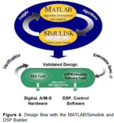
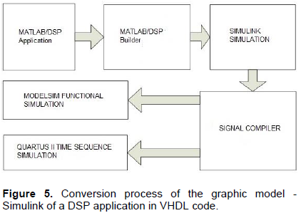
Figure 5 illustrates the conversion process of the DSP application graphic model, created in SIMULINK® with the DSP Builder® libraries, into VHDL hardware description code. When using DSP Builder to complete the design, firstly use MATLAB design and generate a DSP application, then build the model file in MATLAB/Simulink software, simulation design in Simulink and scope module can be used to monitor the simulation results. DSP Builder Signal Compiler module reads the Simulink modeling file built by DSP Builder and Mega Core module, generate the VHDL file and the tool command language script, DSP Builder Test bench module generates test bench file and automatically invoke modelsim for functional simulation, timing simulation using Quartus II.
According to the DTC structure shown in Figure 3, the motor model block, estimation of the flow and torque block, current acquisition, and inverter block are performed and simulated in the MATLAB/Simulink environment. Stator torque and flow controls are performed using the torque hysteresis comparator and flow hysteresis comparator block, which are, along with the vector table block, implemented and simulated in the DSP Builder software.
In the DTC control algorithm block, the motor model calculations and their respective comparisons with their reference values ​​are performed, in addition to determining the space sector where the flow is. The outputs of the hysteresis comparators, in addition to the spatial flow sector, are inputs to the part of the program responsible for the inverter-switching table. This table indicates the best alternative for the DTC at that instant and triggers the inverter keys to maintain the desired control.
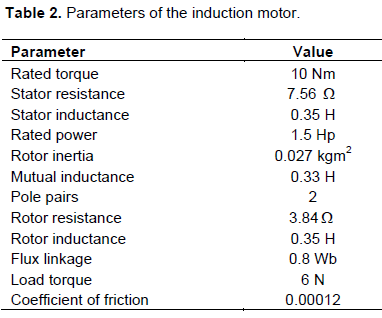
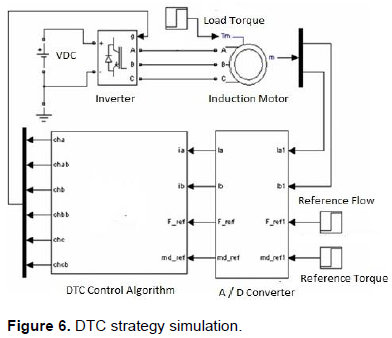
The simulated inverter uses ideal switches, since the IGBT are considered as ideal keys for the frequency level used in the simulation. The switching frequency chosen was 20 kHz. The instrumentation part (A/D converter) was performed and simulated in the MATLAB/Simulink environment. Stator currents enter as binary data in the DTC control algorithm. For resolution of the A/D converter, 16 bits were assumed. The sampling frequency used in the A/D converter was 40 kHz. The control algorithm that controls the motor based on the DTC strategy was divided into two parts. The first part, responsible for the calculations, operates at a frequency of 40 kHz. The second part, which contains the inverter-switching table, operates at a frequency of 20 kHz. Parameters for the induction motors used in the simulation are listed in Table 2. Figure 6 illustrates the DTC strategy simulation.
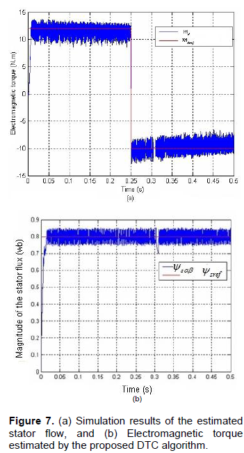
To verify the proposed DTC strategy, simulation results are presented. The simulations are done by using Modelsim 6.5. The Altera DE2-115 board with a Cyclone III device is used to execute the DTC control algorithm. Figure 7a shows the simulation result of the DTC algorithm for positive and negative references of the magnitude of the estimated stator flow and its reference. Figure 7b shows the simulation result of the DTC algorithm for positive and negative references of the estimated electromagnetic torque and its reference. To perform the test on the DTC, a positive reference torque is applied to the induction motor with a reference of 0 N·m during the initialized time, and 10 N·m at 0.25 s.
Comparative results of simulation for MATLAB reference model and VHDL model implemented in FPGA are presented. Figure 8 shows the comparison between MATLAB and VHDL Torque response. A minimum error was observed between MATLAB and VHDL simulation results. This is caused by the differences between the two models. They have the same functionality but the calculations are not the same. Model written in VHDL is based on estimated values of them agnitude and the angle, while in the Matlab model, it use a mathematical functions.
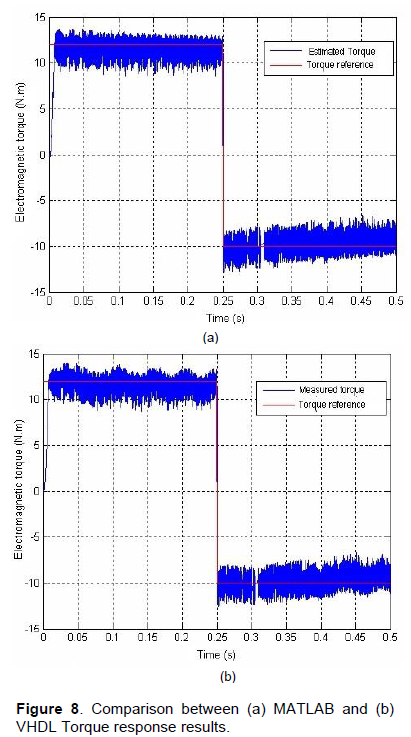
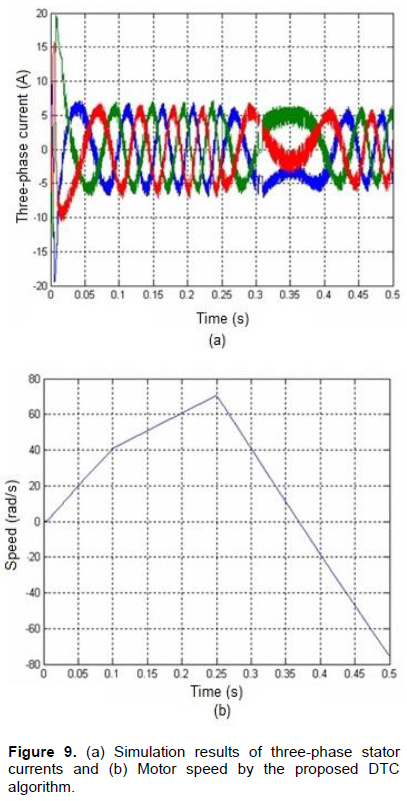
Figure 9 shows the simulation result of the DTC algorithm for positive and negative reference to the stator currents. From Figure 9a, a change can be observed between two phases at a time equal to 0.25 s due to the change in the torque direction of the motor. The period between 0.3 s and 0.4 s shows the behavior of the phase currents when the velocity is reduced. From Figure 9b, the rate of growth of the motor speed changes at 0.1 s when a load of 6 N·m is coupled to the shaft. At a time of 0.25 s, the torque reference changes direction, causing the motor speed to decrease, and after a short time interval it changes its direction of rotation.
This paper presented the digital design and simulation of the DTC strategy using the VHDL language. A DSP design for the motor control was developed and simulated for the particular case of the DTC algorithm of a three-phase induction motor. The real controller is not experimentally tested. A specific methodology, using software configurations and a mixed simulation, allowed the verification of the behavior of the VHDL codes before their implementations on the FPGA device. The methodology defined the digital adaptation of the DTC algorithm, considering the influences of digitization on the computed values. An optimized DSP algorithm and a specific fixed-point format have been studied and defined. The implementation, which proved that the DTC strategy was accomplished using the combination of MATLAB/Simulink and DSP Builder software. This project addressed a method of structuring and simulating a DTC algorithm. The target technology was FPGA, which have been growing steadily and are utilized in the industrial market worldwide.
The authors have not declared any conflict of interests.
REFERENCES
|
Barlas T, Moallem M (2010). Developing FPGA-based embedded controllers using Matlab/Simulink. 1st Edition, Factory Automation,
|
|
|
|
Casadei D, Serra G, Tani A, Zarri L (2013). Direct torque control for induction machines: a technology status review. 2013 IEEE Workshop on Conference Electrical Machines Design Control and Diagnosis (WEMDCD). pp. 117-129.
Crossref
|
|
|
|
|
Da Costa C, Kashiwagi M, Mathias M H (2014). Digital Systems Design Based on DSP Algorithms in FPGA for Fault Identification in Rotary Machines. J. Mech. Ind. Res. 2:1-5.
Crossref
|
|
|
|
|
Ibrahim SO, Faris KN, Elzahab EA (2015). Implementation of fuzzy modeling system for faults detection and diagnosis in three phase induction motor drive system. J. Elect. Syst. Info. Technol. 2:27-46.
Crossref
|
|
|
|
|
Karimi S, Poure P, Berviller, Y, Saadate S (2007). A design methodology for power electronics digital control based on a FPGA in the loop prototyping. 14th IEEE International Conference on Electronics, Circuits and Systems (ICECS), pp.701-704.
Crossref
|
|
|
|
|
Matic P, Vukosavic SN (2011). Direct Torque Control of Induction Motor in Field Weakening Without Outer Flux Trajectory Reference. Intl. Rev. Electrical Eng. 7(2):1204-1212.
|
|
|
|
|
Niu F, Wang B, Babel AS, Li K, Strangas EG (2016). Comparative Evaluation of Direct Torque Control Strategies for Permanent Magnet Synchronous Machines. IEEE Trans. Power Elect. 31(2):1408-1424.
Crossref
|
|
|
|
|
Pandya SN, Chatterjee JK (2010). Torque ripple reduction in direct torque control based induction motor drive using novel optimal controller design technique. Power Electronics, Drives and Energy Systems (PEDES) & 2010 Power India, 2010 Joint International Conference on, pp. 1-7.
Crossref
|
|
|
|
|
Pereira WCA, Aguiar MI, Paula GT, Monteiro JRBA, Bazan GH, Castoldi MF, Sanches DS (2015). Virtual Platform of direct torque control of induction motor to assist in education of undergraduate students. 2015 IEEE 24th International Symposium on Industrial Electronics (ISIE), pp. 814-818.
Crossref
|
|
|
|
|
Perry DL (2004). VHDL Programming by Examples. New York, NY, USA: McGraw-Hill, 2004.
|
|
|
|
|
Soufien G, Abdellafit M, Mohamed FM (2015). Design and experimental Implementation of DTC of an induction machine based on Fuzzy logic control on FPGA. IEEE Trans. Fuzzy Syst. 23(3):644-655.
Crossref
|
|
|
|
|
Sandre-Hernandez O, Rangel-Magdaleno JJ, Morales-Caporal R (2016). Implementation of direct torque control for a PM synchronous machine based on FPGA. 13th International Conference on Power Electronics (CIEP), pp. 155-160.
Crossref
|
|