ABSTRACT
Much research has been done in developing techniques for identifying the structural damping of physical systems. Such techniques are always accompanied by the development of an analytical model of the ideal system and its comparison with experimental data obtained in laboratory. Also, flexible systems are difficult to be modeled, but the authors can use an approximation, supposing that a flexible system, composed by a cantilever beam, can be similar to a massa-spring-damper system. In this work, are shown a recursive technique for identifying the structural damping of a physical system and its applications. The authors identified the structural damping of a system consisting of a flexible beam clamped where the authors use a mass-spring-damper model to represent it. The excitation of the system was carried out using an impact hammer in order to use such data at the input of the analytical model obtained for the system. For the flexible system, the authors implemented the methodology of recursive Kalman’s filter, in order to identify the flexibility and damping coefficients. The results show that the technique has been successfully applied once the error obtained by comparing the experimental and analytical data is quite small.
Key words: Identification, modeling, structural damp, Kalman filter.
The area of identification of damping of physical systems still has several questions to be answered by the scientific community. The effects of damping are well known, but its precise characterization is still an unsolved problem. In Pilkey et al. (1997), the authors propose two methods for identification of damping, an interactive and another that uses the method of least squares. In Adhikari (2002), the author proposes a method, based on the poles and waste measurements of transfer functions associated with the method of Lancaster. In Pradhan and Modak (2012), the authors address the issue of identification of damping matrix of a structure by posing it as a finite element damping matrix updating problem. According to the authors, the formulation developed seeks to separate updating of the damping matrix from that of updating of the stiffness and the mass matrix, reducing the difference between the complex FRFs. In Andrianne and Dimitriadis (2012), the authors show a new technique to identify the damping of linear systems. The ability of such technique to estimate the mode shapes and the modal damping is demonstrated, by the authors, on a simulated mass–spring–damper system. In Arora (2014), the author proposes and tests a new structural damping identification method using normal frequency response functions which are obtained experimentally. According to the author, the test has the objective that the damped finite element model is able to predict the measured FRFs accurately.
In Pan and Wang (2014), the authors outline a complex mode procedure for identifying the exponential damping model and discuss its applicability and limitations. Also a new iterative method for relaxation factor is proposed, without using the full set of modal data. The authors also state that the finite element model updated method for the systems with exponential damping can predict accurately not only the natural frequencies but also the FRFs of the systems. In Arora (2015), the author proposes a method, which is a FRF-based method and overcomes the problem of closely spaced modes for damping identification. The author also states that the accuracy of identified structural damping matrix depends upon the accuracy of finite element model. To address this issue, in this paper was set up a simple experiment in the Vibration Laboratory, Department of Mechanical Engineering at University of Taubaté (UNITAU). The experiment used as input an impulse from an impact hammer, whose calibration is performed in the laboratory. The experiment consists of a flexible beam instrumented with an accelerometer on its free tip and also excited by the impact hammer.
This paper presents the analytical modeling of the physical system, together with studies to validate its models through experimental tests and studies of parametric identification of the parameters of the systems in the time domain. An impulse (applied by the impact hammer) excites the beam and the excitation of the tip of the beam, measured by an accelerometer, is acquired for further analysis. In order to do the system’s parameters identification, the authors implemented a recursive Kalman filter, using the Octave software. Preliminary results show a good agreement between experimental and analytical models, leading us to conclude that the computational procedure works quite satisfactory.
CALIBRATION OF THE IMPACT HAMMER
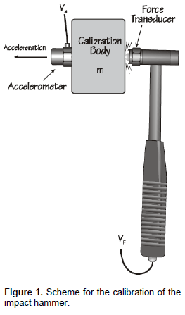
Aiming to increase the reliability of the experimental data, the authors chose to calibrate the impact hammer in the laboratory, setting up an experimental set-up consisting of a known mass and a capacitive accelerometer (model MMA1220D Micro machined Motorola), previously calibrated (the accelerometer sensibility was supplied by the manufacturer), as illustrated in Figure 1.
This experiment is suggested by the equipment manufacturer (PCB Piezotronics) and involves the application of Newton’s 2nd law to the result of applying an impulse to a known mass:

Writing the equations in terms of the sensibility of the accelerometer and impact hammer, the authors have:
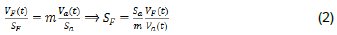
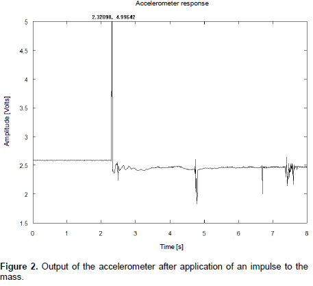
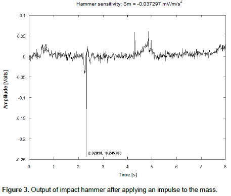
In Equations (1) and (2), a is the acceleration of gravity. F is force, m is the mass used in the experiment (m=200.23g), VF is the voltage peak value registered by the impact hammer, SF is the sensitivity of the impact hammer, Va is the voltage peak registered by accelerometer and Sa is the sensitivity of the accelerometer, supplied by the manufacturer (Sa=250mV/g). Figures 2 and 3 illustrate the temporal response of the impact hammer and the accelerometer, after the application of an impulse to the mass.
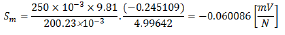
Replacing numerical values in Equation (2), the authors obtain:
Once given the sensitivity of the impact hammer, the experiment was assembled as described in this research.
IDENTIFICATION OF A STRUCTURAL DAMPING OF A CANTILEVER BEAM
Approximate mathematical model of a cantilever beam
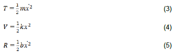
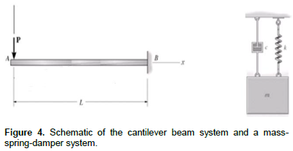
The simplified model of a simple cantilever beam, shown in Figure 4 can be obtained comparing it to a mass-spring-damper system. Damping constant b is due to structural damping of the beam, and flexibility is given by k. Writing kinetic, potential and dissipation energy of the system, the authors have:
Using Lagrange’s equations Wellstead (1979), one obtains the model described by the classical Equation (6).
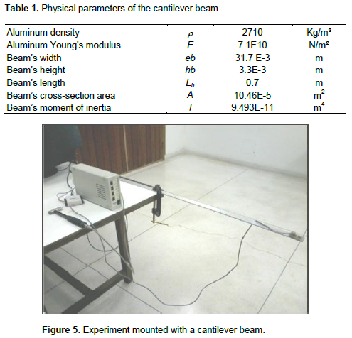
Where f(t) is an external force applied to the system to excite him. In the Laboratory of Mechanical Vibrations, an experiment was set up with a cantilever beam, with the characteristics described in Table 1.
The data acquisition equipment was composed by a capacitive accelerometer (model MMA1220D Micro machined Motorola), connected to a signal acquisition board (NI USB-6009 from National Instruments) connected to a USB port on a PC compatible. The experimental data acquisition program was developed using the graphical language LabView ®. The accelerometer was attached to the free tip of the beam and the system was excited with an impulse applied to the impact hammer (Figure 5).
Digital filtering and numerical integration
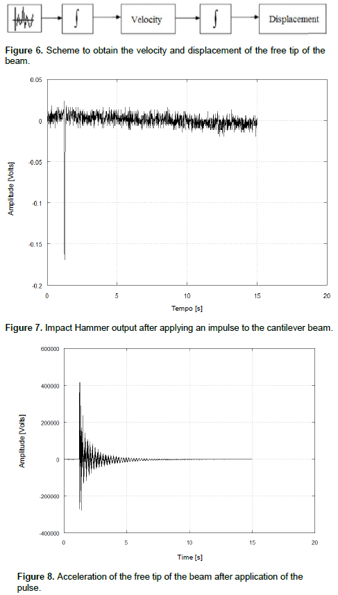
Accelerometers are sensors widely used in engineering applications. It can be helpful to perform modal analysis and many others analysis in frequency domain. If the authors are not concerned with the signal amplitude, this analysis could be done without worries. In this case, the authors are interested to have a precisely measurement of a velocity and displacement at the position where the accelerometer was located. This will lead us to be sure that the signal amplitude is correct. Also, the authors need to perform a numerical integration of the signal twice. Figure 6 represents a scheme about what the authors implement at first.
The filter that the authors choose was a high pass Butterworth with five terms and cutoff frequency in 5Hz. Those values were chosen empirically. To reach at the results, the authors used the routine available in Octave® software, called butter, which designs the filter by calculating its coefficients and the routine filter which applies the calculated coefficients to the signal. The numerical integrator used, implements the Trapezoidal Rule and the authors used the routine also available in Octave® software called trapz. Figure 7 and 8 illustrate the results of the application of an impulse to the cantilevered beam.
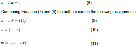
For the identification of damping parameter (b) and flexibility parameter (k) of the cantilever beam, the authors used the technique of recursive Kalman filter (Bierman, 1977). For the assembly process, Equation (6) should be rewritten as:
In Equation (7), the values of

and
f(t) are the output of the accelerometer and impact hammer respectively and the values
and
x were obtained by integrating twice the signal from the accelerometer, like previously mentioned. The system was therefore placed in the form:
And V is the error associated with the observations.
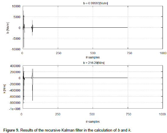
The recursive Kalman filter algorithm (Appendix A), implemented in Octave software version 3.0.0, has calculated the following values for
k and
b, respectively: 216.29

and 0.99693

. The graph (Figure 9) shows the robustness of the method, which converge shortly after the sample number 200of 1000 samples considered.
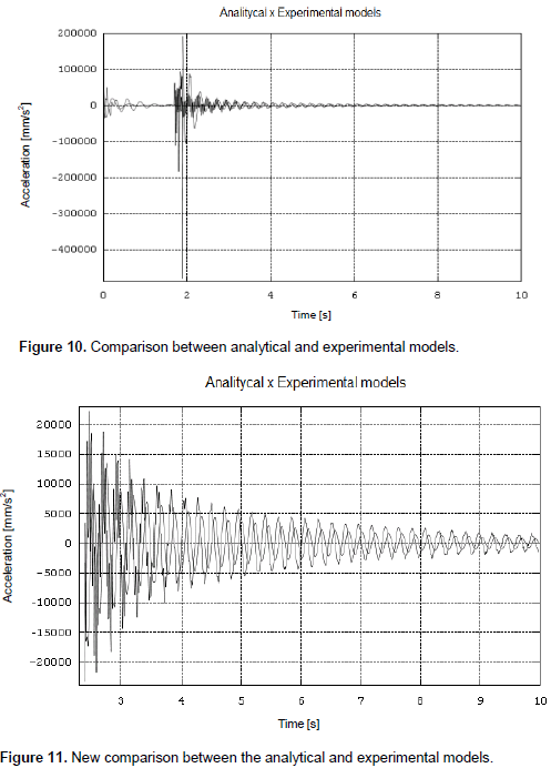
With the parameters identified, the authors compare the analytical model, given by Equation (6) and the experimental model in the graphic illustrated in Figures 10 and 11.
Figure 11 also shows the comparison of the results but with a more favorable range, in order to highlight the agreement between the experimental and analytical results.
The identification of the damping in flexible systems is still a challenge to be overcome. The use of a recursive technique shows that it is possible to reach a reasonable estimation with a reliable method, the recursive Kalman filter. The technique is very simple to implement and show a very nice convergence using only a few samples.
CONCLUSIONS AND FURTHER WORK
This paper presents the identification of the damping and flexibility parameters of a physical system composed by a cantilever beam. To validate the identified parameters a representative experiment were assembled in laboratory. The experiment was monitored using the LabVIEW software and a data acquisition board (NI USB -6009 manufactured by National Instruments). The authors implemented the method of recursive Kalman filter to identify the damping parameters (b) and flexibility (k) of the system. Results obtained show (Figures 10 and 11) good agreement between the analytical model and experimental, suggesting success in the identification. The work is in progress and proposals for its continuation are: (a) work with an even simpler system with concentrated parameters, but with more degrees of freedom and (b) using the full model (distributed parameter) of the cantilever considering their flexibility and degrees of freedom and carrying out the identification of the structural damping matrix.
The authors have not declared any conflict of interest.
REFERENCES
|
Pilkey DF, Roe KP, Inman DJ (1997). Computational Issues in Damping Identification for Large Scale Problems, Proceedings ASME Design Technical Conference, paper No. DETC97/VIB-3835, September. |
|
|
Adhikari S (2002). Lancaster's method of damping identification revisited. J. Vib. Acoust. P. 24.
Crossref |
|
|
|
Pradhan S, Modak SV A (2012). Method for damping matrix identification using frequency response data, Mech. Syst. Signal Process. 33:69-82. ISSN 0888-3270.
|
Andrianne T, Dimitriadis G (2012). Damping identification of lightly damped linear dynamic systems using common-base proper orthogonal decomposition, Mech. Syst. Signal Process. 28:492-506. ISSN 0888-3270. |
|
|
|
Arora V (2014). Structural damping identification method using normal FRFs. Int. J. Solids Struct. 51(1):133-143. ISSN 0020-7683. |
|
|
|
Arora V (2015). Direct structural damping identification method using complex FRFs. J. Sound Vib. 339:304-323. ISSN 0022-460X. |
|
|
|
Bierman GJ (1977). Factorization methods for discrete sequential estimation", Academic Press Inc., New York. 241 pp. |
|
|
|
Wellstead PE (1979). Introduction to Physical System Modelling, Academic Press. |
|
APPENDIX
A – Recursive Kalman filter routine
function [x,P] = kalman(x,A,z,N,P);
sigma = 1;
delta = z;
for i=1:N,
v(i) = 0.0;
for j=1:N, v(i) = v(i) + P(i,j)*A(j); end;
delta = delta - A(i) * x(i);
sigma = sigma + A(i) * v(i);
end;
% t t
%Comment : v = PA , sigma = APA + 1, and
% delta = z - Ax have been computed
%
sigma = 1.0/sigma;
for i=1:N,
K(i) = v(i) * sigma; % Kalman gain
x(i) = x(i) + K(i) * delta;
for j=1:N, P(i,j) = P(i,j) - K(i)*v(j); end;
P(j,i) = P(i,j); % utilized simmetry
end;
% Comment : Kalman gain, updated estimate and
% optimal covariance have been computed
%
for i = 1:N,
v(i) = 0.0;
for j=1:N, v(i) = v(i)+P(i,j) * A(j); end;
end;
for j=1:N,
for i=1:j,
s = 0.5 * (P(i,j) - v(i) * K(j) + P(i,j) - v(j) * K(i));
P(i,j) = s + K(i) * K(j); % stabilized update
P(j,i) = P(i,j);
end;
end;