ABSTRACT
An unexpected (premature) failure happened in Tail Pulley during operation in field. Consequently, a complete analysis in terms of fracture and fatigue performed. The analysis aimed to determine the failure root-cause by the analysis of the project and materials. The analysis covered the tensions undergone by the pulleys under operation and the material´s mechanical strengths. The results showed the project conforms the classical mechanics calculations. The failure, on the other hand, characterized as ductile fracture – Fatigue - with crack propagating along 45° referencing the cylinder longitudinal axis. The crack initiated at a flaw found at the weldment region, which resulted a shorter lifetime (collapsing). The sharpen flaw generated a shortcut in the failure process and jumped it straight to the phase of fracture - Stage II fatigue – called crack propagation.
Key words: Tag pulley, stress raiser, critical stress, fatigue.
Mechanical failure of components is always detrimental to equipments and machines and sometimes catastrophic. In the mining or quarry segments failures bring huge prejudices to companies due to downtime (sometimes production impossibility) and costs involved in corrective maintenances. Pulleys are essential to support and allow the conveying of materials and minerals back and forth in the production. Therefore their failures generate always long stoppage in production. A deep analysis of the failed part is notoriously important to preventively avoid recurrence of such event. In this context, the design reanalysis and a “practice x theory” approach when covering wide aspects involved in the failure are mandatory to investigate its real root cause. According to Martins et al. (2009) and Dieter (1986), materials under dynamic cycling are sensitive to stresses state; consequently during the field analysis any flaw in the design or part may be neglected.
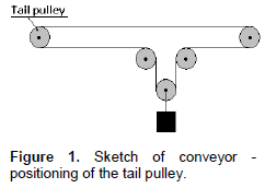
According to information’s obtained in field the tail pulley collapsed abruptly and during operation (sees its positioning on the conveyor - Figure 1). The characteristics of the pulley application are; belt conveyor - belt width 762 mm, tensions T1 and T2 185 kN and wrapping angle of 180° on the pulley cylinder. The pulley has an outside diameter of 500 mm, body length (cylinder) 860 mm, and distance between the bearing blocks 1200 mm, shaft diameter at the bearing blocks of 100 mm. The expansion ring used in order to fix and lock the shaft to the pulley hub (its body) was Ring-Feder model 7012, internal diameter 110 mm. This paper aims to analyse the pulley in terms of design, material application and manufacturing, determining the root cause of its abrupt collapse during operation. The study covers the design re-evaluation, the material chemical, metallographic and mechanical property analysis, and the failed surface mapping.
Project analyze
The previous calculations done in the design phase were traceable and re-analyzed against the belt conveyor tensions, the material used in the project and the stresses obtained for each component in the assembling. The safety factors identified and compared with the materials mechanical strength and fatigue strength. The residual stresses generated by the welding were not taken into account once the pulley undergoes stress relieve treatment after the manufacturing process. The equations used to evaluate the design of the pulley are those belonged to the classical mechanical equations.
Metallographic analysis, chemical composition and hardness
The chemical and metallographic analysis of the materials of the cylinder and disc succeed in agreement with standards. The purpose was to verify the conformity of both materials with the standard ASTM A-36. The methods to this verification were the electronic microscopy, metallography with etching by Nital 3%, and the Energy Dispersive X-Ray Spectroscopy (EDS) in order to quantify the steel chemical components. The hardness measured in Brinell hardness scale and in a region 200 mm far from the weldment zones.
Mapping the failed surface
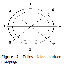
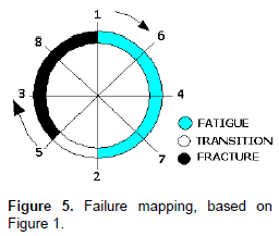
Priory of analyzing the failed surface of the cylinder it was cleaned up with the appropriated chemical product (Hydrodesulfurized Heavy). The impregnated particles on the fractured surface were brushed-removed by hand with a steel cord brush. The surface was mapped along 360° and the regions of failure examined microscopically by naked eye. The mapping of the fractured surface followed the sketch at the Figure 2. Pictures were taken from the failure surface (for each region), prioritizing those regions which presented the lesser plastic deformed condition and damages.
Beyond the procedure described, the cylinder sheet was analyzed in terms of quality of weldment. A sample was taken from the cylinder by cutting, grinding and polishing it and then etching with Nital. The intention was to verify the presence of any flaw along the weldment length or cross section. Flaws like discontinuities, voids or cracks, which could lead to failure.
Fracture toughness and fatigue
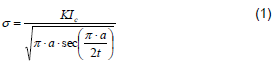
The component discontinuity dimensions serve as inputs to determine its damage to the component in usage (under load). The mathematical modeling considers the stress intensity for a partial-through thickness flaw, which is given by Dieter (1986), Rabinowicz et al. (2008) and Paris and Erdogan (1963), like follows:
As a rule, whether the critical stress level (s), in order to make the detected flaw to propagate to failure is lower than the applied stress (sa) - in other words (sa) is not reached, the flaw won´t propagate as a brittle failure, as follow:
- s > sa = the crack won´t propagates to failure;
- s £ sa = stable, it will propagate to failure.
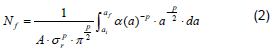
It is usual in engineering context to place fatigue crack propagation versus the crack length versus cycles at a series of different stress levels, expressed by a general plot of da/dN versus DK (NASA (1990) and Beden et al. (2009) and Reed et al.(1973). Equation (2) is the appropriate integration to this case. The critical crack length, af, at which catastrophic failure can occur (life termination) can be calculated from the following equation:
The equation above is due the Stage II of crack propagation and occurs by a plastic blunting process. At the start of the loading cycle the crack tip is sharp, as the tensile load is applied the small double notch at the crack tip concentrates the slip along planes 45° to the plane of the crack.
Project analyze
After the re-analysis of the design, the calculations are correct and appropriate to the application; the materials properties based on Standard and fatigue limits based on classical technical literature (Beden et al., 2009; Ullman, 1992; Pahl and Wolfgang, 2013). The shaft of the pulley under load presents low stress and deflection, when calculated by Finite Element Method (FEM). The other components, discs and the cylinder are also under low stress levels and appropriate to the application. All stresses respect the safety factors defined previously by the manufacturer based on the project procedures, dictated by the company technology (Table 1).
Metallographic analysis, chemical composition and hardness
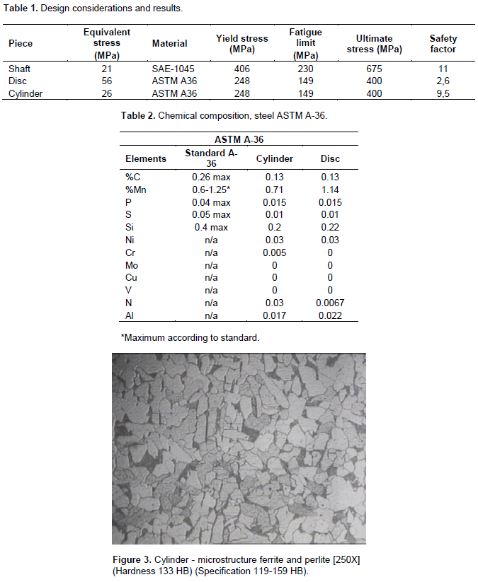
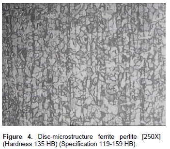
The elements quantity in weight and chemical composition are in the Table 2. The material chemical analysis revealed that the materials conforms the standard ASTM A-36. The elements Ni, Cr, Mo, Cu, V, N and Al, as known, are considered residuals into the material, and do not jeopardize its metallurgical or mechanical functions in the application. Figure 3 presents the microstructure of the material A-36 used in the cylinder. Figure 4 presents the same material but now of the discs.
Both, cylinder and disc, present the specified and expected microstructure ferrite and perlite and in accordance with ASTM A36 (Ashby and Cebon, 1993; Metso specification, 1998; Roberts et al., 1988). Any segregation, unexpected microstructure nor cracking were found. The expected hardness at the discs and cylinder are within the specification tolerance. The discs hardness was 135 HB while the cylinder 133 HB, both conform the material hardness specification.
Mapping the failed surface
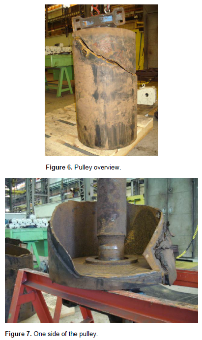
Figure 5 presents an overview of the mapping of the fractured surface of the pulley, while Figure 6 the two broken parts of the pulley rearranged for a better visualization. Figure 7 just ahead shows only one of the shorter pulley failed piece also for a better comprehension.
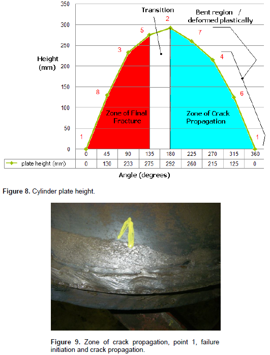
From the Figures 6 to 8 seen that the fracture is macroscopically characterized - by naked eye- as ductile fracture due the crack path (crack propagation, phase II) around 45° (Dieter, 2008). The graph in the Figure 7 maps the height of the fractured cylinder measured from the cylinder face, versus its angular position, separating the different zones along the circulararea. As seen the maximum height of the cylinder was 292 mm to an angular position of 180° (Figure 8).
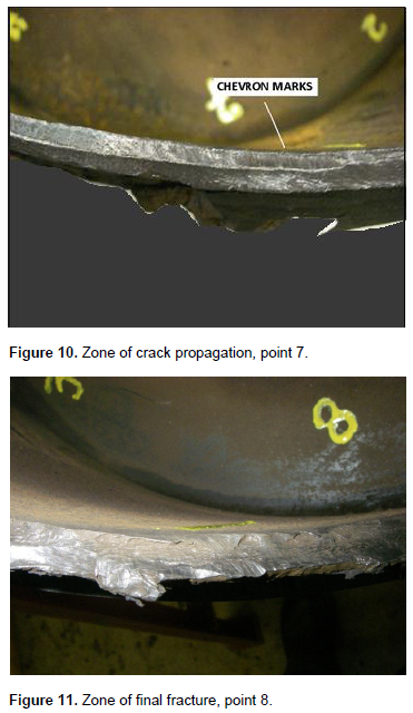
Failure analysts usually investigate the fracture path to determine the fracture initiation and termination sites, as well as other fractography features. Based on this information, the analyst can also identify various types of monotonic (single cycle) overload, fatigue (multiple cycle) cracking, and time-dependent (creep or corrosion) failure, or combinations thereof (Michael et al., 2007; Richard, 2011). Figures 9 to 11 aims to reveal the aspects of each of the mapping zones identified in the chart of the Figures 5 and 8.
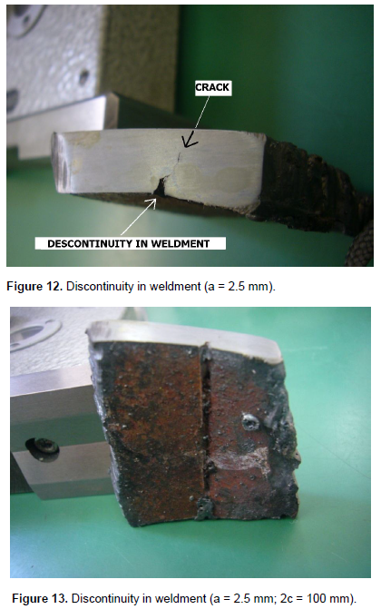
After a detailed investigation at the failure initiation region and taking a small sample from the cylinder to analyze, one discontinuity found in the zone of crack propagation and particularly close to the crack starting point, at the cylinder longitudinal weldment, more precisely at the interface between disc and cylinder (Figures 12 and 13).
Fracture toughness and fatigue
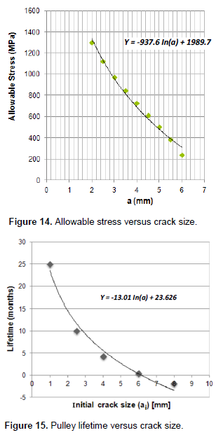
Figure 14 reveals that the crack dimension despite of being large when compared with the cylinder thickness (Figure 13), a = 2.5 mm, c = 100 mm against t = 6.35 mm (cylinder thickness), it does not lead to the final fracture, particularly for brittle fracture. The compilation of high material fracture toughness value (KIc), big crack size and low stress on the cylinder, based on Equation 1 and Table 1, shows the impossibility of brittle fracture. Therefore, the yielding starts a process of slipping planes at the discontinuity, pre-requisite for the Stage I of structural fatigue, called Crack Initiation.
With the fatigue Stage I established due to the pre-existing flaw, it is right to expect a substantial decrease in the lifetime of the pulley under fatigue. As already well established in the literature, this initial fatigue stage theoretically consumes around 80% of the total lifetime of the component to fracture (Figures 10 and 11). Soon after this stage, the crack growths, stage II, and the crack moves instantaneously and fast – consuming the remaining 20% of the total lifetime. The calculated crack growth based on Equation (2) and traced on Figure 15, describes the component (cylinder-pulley) lifetime versus the initial crack size. As described, the low stress at the cylinder, the large crack size and the high KIc value contribute detrimentally to the cylinder failure. It makes the failing to jump for the crack growth, stage II, which speeds up the failure process. The same figure makes clear that flaw (considered stress raisers) with dimension equal of 3.0 mm theoretically results in a lifetime of 10 months. For flaws equal or bigger than 6.0 mm these will not support the application. It means, when loaded into the conveyor the component fails whether just starts being cyclically loaded.
The customer traceability record demonstrates the pulley real lifetime under application in the field as 09 months, pretty close to the theory applied in the analysis.
1. The pulley design is according to the allowable stresses and based on the materials properties;
2. The materials conform with the characteristics in the standard and specification; chemical composition, microstructure and mechanical property (hardness);
3. The failure is not characterized as brittle fracture;
4. Due to the stress raiser (flaws in the weldment zone) the material yield at the crack tip and speed up the fatigue process. Being the Stage I already accomplished due the flaw presence the fatigue phenomenon jumped straight to the Stage II, crack propagation;
5. Failure micromechanics of chevrons and beach marks found at the failure surfaces reinforce the fatigue presence;
6. The fatigue is characterized as ductile and under low stresses, once the Stage II extends till 180o of the fractured surface;
7. The crack started at the weldment intersection between the disc and cylinder, at the sharpen flaw in the cylinder;
8. The final facture consumed 180° of the fractured surface;
9. The discontinuity presented in the weldment region was the root cause to the fatigue;
10. Comparing the calculated lifetime with the real pulley running in field both are quite similar (calculated - 10 months x real - 09 months).
It is highly recommendable for pulleys but also for all mechanical parts under cyclic loading to have a detailed manufacturing procedure. This procedure must cover all the processes parameters and follow its monitoring and registration along the manufacturing steps. At this manner a more traceable and reliable product is accomplished.
The authors have not declared any conflict of interest.
The National Council of Scientific Development and Technology, CNPq, Brazil, (Proc. 408250/2013-5) and FAPESP (Proc. 2014/06679-8) supported the present work.
REFERENCES
Ashby MF, Cebon D (1993). Materials selection in mechanical design. Le J. de Physique IV 3.C7: C7-1.
Crossref |
|
|
|
Beden SM, Abdullah S, Ariffin, AK (2009). Review of Fatigue Crack Propagation Modelsfor Metallic Components. Eur. J. Sci. Res. ISSN 1450-216X. 28(3):364-397. |
|
|
|
Dieter GE (2008). Mechanical MetallurgyHardcover - Apr. 1. |
|
|
Martins JA, Kovesdy I, Ferreira I (2009). Fracture analysis of collapsed heavy duty pulley in a long-distance continuous conveyors application. Eng. Fail. Anal. 16:2274-2280.
Crossref |
|
|
|
Metso specification (1998). Material A-36, Chemical and Mechanical Properties. |
|
|
|
Michael JM, Griebel AH, Tartaglia JM (2007). Fracture surface analysis. Advanced Materials and Processes. |
|
|
|
NASA Technical Memorandum 102646 (1990). A Compendium of Sources of Fracture Toughness and Fatigue Crack Growth Data for Metallic Alloys - Part IV. |
|
|
|
Pahl G, Wolfgang B (2013). Engineering design: A systematic approach. Springer Science and Business Media. |
|
|
Paris PC, Erdogan F (1963). A critical analysis of crack propagation laws. J. Fluids Eng. 85(4):528-533.
Crossref |
|
|
Rabinowicz Y, Roman I, Ritov Y (2008). Advanced methodology for assessing distribution characteristics of Paris equation coefficients to improve fatigue life prediction. J. Compilation Blackwell Publishing Ltd. Fatigue Fract. Eng. Mater. Struct. 31:262-269.
Crossref |
|
|
|
Reed H, Robert E, Reza A (1973). Physical metallurgy principles. Fourth Edition. Cengage Learning India. |
|
|
|
Richard GB (2011). Shigley's Mechanical Engineering Design. Published by Tata Mcgraw Hill Education. |
|
|
|
Roberts AWD, Papaliski R, Harrison A (1988). The friction and tension characteristics on driving drums of conveyor belts." Proceedings, 12th Intl. Power and Bulk Solids Handling Conference, Chicago, USA. |
|
|
|
Ullman DG (1992). The mechanical design process. New York: McGraw-Hill. 2. |