Full Length Research Paper

ABSTRACT
This paper investigates the use of a Genetic Algorithm to produce an optimized compact monopole antenna for textile application. The antenna characteristics are examined using the Numerical Electromagnetic code (NEC2) with genetic algorithm (GA). The design objective for the antennas considered here is to drive the S11 to be less than or at least, as close as possible to -10dB, targeting this application (850-950 MHz) band. Results of return loss are also presented. The purpose of this study is to build a genetic algorithm (GA) optimisation of wire antennas for application at 900MHz. These antennas are fully textile, flexible and wearable. Measurement test was performed by placing the textile antenna sample close to the human chest while results were compared with simulation on a body phantom. Specific absorption rate was evaluated in CST Microwave Studio. To validate our results, four linear wire antenna designs, planar and embroidered antennas were fabricated, measured and compared with the simulation. Simulated and measured results show that all the antennas can operate at 900 MHz band.
Key words: Genetic algorithm, linear wire, segment length, population, chromosome, specific absorption rate.
INTRODUCTION
Antennas are amongst the most essential components in any wireless system, as they transform a signal that flows through wires into an electromagnetic wave that propagates through free space. A good design of the antenna improves the overall system performance as presented by Balanis (2016). Antenna design is performed either empirically or via simulator using nu-merical method. These are broadly classified into those based on the integral or differential form of Maxwell’s equations. The former typically produces frequency domain solution and the latter time domain. Using genetic algorithm (GA) with electromagnetic simulation, antennas are designed based on wire configuration. Genetic algorithms are used to explore the design domain and automatically discover a novel antenna design that can be more effective than would be developed (Altshuler and Linden, 1997). Genetic algorithms are numerical algorithms modeled on the concepts of natural selection and evolution theory that modifies and optimizes results among several generations. GAs operates on a population of potential solutions applying the principal of survival of the fittest to produce better and better approximations to a solution (Choi et al., 2015).
Genetic algorithm has been successfully applied to crooked-wire antennas, planar wire antennas, zigzag patterns, mender-line and even fractal geometries (Johnson et al., 1997; Ghatak et al., 2009). Genetic algorithm has been applied to designed and optimized antenna problems like microstrip spiral antenna with 6 and 10 segments (Mehrparvar et al., 2012), wire antennas with 4 segments and crooked-wire genetic antenna with 7 segments (Hornby et al., 2006) and small wire antennas with 7 segments (Altshuler and Linden, 1997). In this study, the methods of multi-segments wire struc-ture are used coupled with genetic algorithm for wire antenna design (Choo et al., 2002). This antenna design is achieved through the unique approach of bending /meandering the antennas to reduce the size and give it a compact design. In this paper, the design parameters are real values which are mapped into a chromosome (that is a representation of the design). In this study, the real valued GA was used in contrast to most studies that used binary implementations (Altshuler and Linden, 1997; Jagodzinska et al., 2008).
Textile antenna has been developed into flexible and light weight to be integrated into clothes (Zhang et al., 2012). This wearable antenna samples can be retrofitted into garments for application of global system for mobile communication (GSM). The wearable textile is designed for application as a pocket antenna at 900 MHz frequency. These antennas consist of two parts: the radiating element and ground plane made of conductive threads on a Denim substrate. Using this substrate makes the antenna light, flexible and relatively inexpensive. For this application Amberstrand 66 is used as the conductive thread.
OPTIMISATION METHOD
Identifying parameters is the first step in any optimization procedure for antenna design. In this study, three parameters were required namely the segment, angle between segment and the radius of the wire. A mathematical model was developed and demonstrated with a 7-segment parameterized antenna structure using MATLAB. The geometry of the proposed antenna is presented in Figure 1. The antenna consists of 7 segments and 5 angles between the segments. The ground is a linear wire of radius r and given as l6+ l7. The total length of the antenna lT is 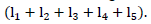 Each segment of the wire is defined by starting points and endpoints. Chromosome is represented as
  In this paper, GA is used with NEC2 to design 7 segments and 5 angle linear wire antenna within the 850- 950 MHz frequency band. The first step in applying GA is to create an initial population using random number generation and assign a random value from the domain of each chromosome. The aim of random selection is to ensure that the initial population is uniformly distributed in the entire search space.
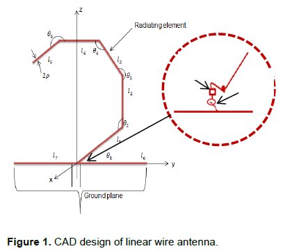
The random values suggested for each parameter in the chromosome are created within a defined range for each parameter as in λ/40 ≤ Segment length ≤ λ/15 and 300 ≤ Segment angle ≤ 600 to define the GA search space. The limits of these angles are chosen to avoid overlapping leading to meaningless results. Figure 2 shows the operation of the genetic algorithm with NEC2.
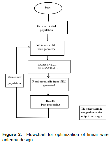
The fitness function is formulated for the maximum return loss around the desired frequency at 900 MHz. Fitness values show the difference between the good and worst solutions by mapping the solution to a non-negative scaling. The fitness value is obtained from objective function values through ranking. Everyone in the suggested population of solutions is assigned fitness. Equations 1 to 3 define the fitness function,
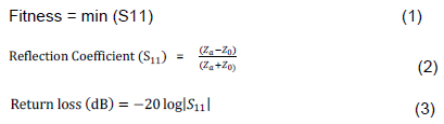
Where, the input impedance Za=Ra+jXa, Ra, is the resistance; Xa is reactance; Z0 is the characteristic impedance of the transmission line feeding the antenna at 50 Ω.
The crossover operator is a method for sharing information between chromosomes; it combines the features of two parent chromosomes ?(C1 and C2) to form an offspring (H1 and H2) as in (4)-(6). In practice, all parents in the mating pool are not selected depending on fitness for crossover operation so that some of the good strings may be preserved. Offsprings are produced according to the rule (Deep et al., 2007):
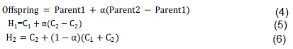
Where, α is the scaling factor chosen uniformly at random over an interval [-0.25,1.25] for each variable of a new offspring. Selection for reproduction was based on the fitness weight. Non-uniform mutation is used in the real coded GAs. Mutation creates a new individual from only one chromosome by altering one or more genes in the search space. Mutation is achieved, to ensure that the population is not trapped in the local minimum. The two individuals (offspring) resulting from each crossover operation will now be subjected to mutation operator in the last step to form the new generation, the mutation probability occurs at 1% (Deep et al., 2007) (Figure 2).
RESULTS AND DISCUSSION
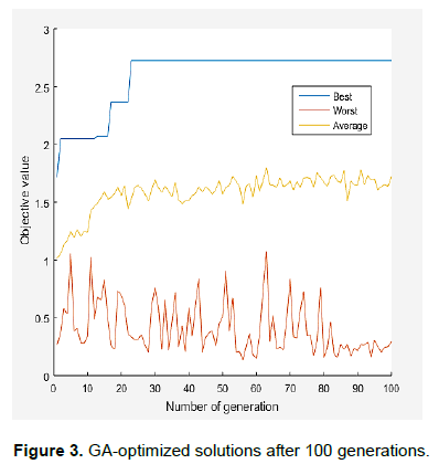
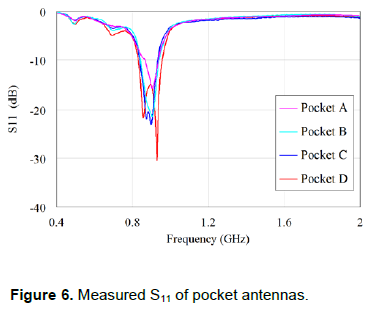
GA optimization involves randomized operators and many evolutions were reaching for an optimum solution. Figure 3 illustrates the average progression of the GA optimization toward an optimum over 100 generations. Average fitness value at any iteration shows the hill clim-bing from 1.2 to 2.5 and was constant; about 2.7 there are no improvements in fitness. All the four antennas with different configurations were referred to as optimized linear wire antennas. The antennas were fabricated using a copper wire of radius 0.8 mm based on the optimized results. These four linear wire antennas exhibit similar resonant properties with center frequency 898 MHz: the design frequency -1.954dB at 497.50MHz and -4.977dB at 691 MHz. The measured S11 of the four linear wire antennas are: Pocket A, -15 dB at 903 MHz with 70 MHz of 10 dB bandwidth; Pocket B, 22.83 dB at 897 MHz with 10 dB bandwidth of 102 MHz; Pocket C, -21dB at 901 MHz with 10dB bandwidth of 110 MHz and Pocket D, -30.05 dB at 930 MHz and 10 dB bandwidth of 127 MHz. The representative antennas were selected from the best 4 antennas at 40th generation in terms of S11. The antenna samples were named pockets A, B, C and D as (Figure 4). All the four antennas with different configura-tions were referred to as optimized linear wire antennas.
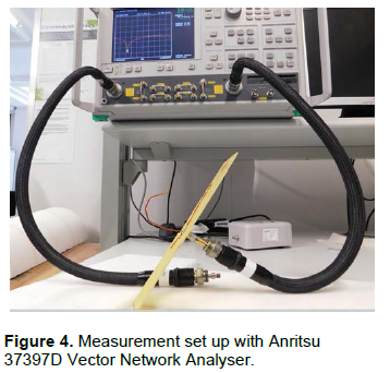
The antennas were fabricated using a copper wire of radius 0.8 mm based on the optimized results. Experi-ments were conducted using 37397D VNA for measuring scattering parameters (S11) of the designed antennas (Figure 4). The working frequency range of 400 to 2000 MHz was selected and the VNA was calibrated using Anritsu 36582 KKF Autocal® module for standard short, open and 50Ω load to minimise instrument errors and achieve the best possible results.
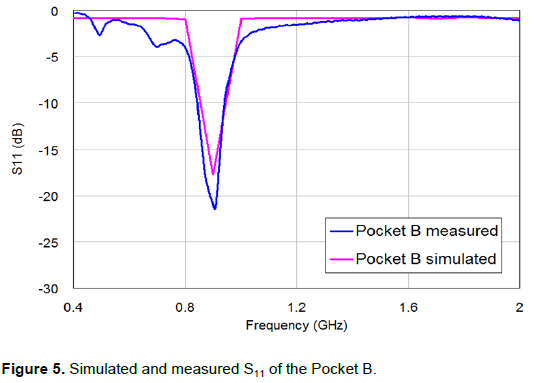
The magnitudes of S11 versus frequency (also known as return loss) for the 4 sample of optimized Pocket antennas are shown in Figure 5. Most of the radiated power of the 4 sample antennas were within 850-950 MHz. The measured return loss of optimized linear wire showed impedance bandwidth with reference to 900 MHz that covers the required bandwidth of the GSM system. These four linear wire antennas exhibit similar resonant ((λ⁄4 in length) properties with center frequency 898MHz.
Antenna pocket B and pocket C exhibit similar performance characteristics except that their differences match.
The dielectric property of the textile (denim sample) was characterized using split post dielectric resonator at 1101 MHz (closest frequency to 900 MHz in terms of measurement). It is possible to evaluate the MUT using either a VNA or Q meter connected to the SPDR. The Q meter measures the S21 results using split post dielectric resonator without a vector network analyser. Permittivity and loss tangent of the denim sample were extracted and used for the simulation in CST Microwave. The dielectric measurement result of the single layer denim is thickness 0.85 mm ![]()
![]()
Embroidery was chosen as the method for fabrication of stitched antennas because digital embroidery is fast and flexible in pattern generation and the integration of high frequency systems into clothing (Seager et al., 2013) (Figure 6). Stitch antennas do not require glue or cutting or lamination processes; only stitching the design onto the fabric. Antenna designs are converted into a format compatible with an embroidery machine for production. In embroidery, patterns are superimposed onto an existing fabric and a stitch design is created. This technology provides high speed, ease of manufacturing, accurate and easily modified stitch antennas. Antennas are automatically integrated into fabric through this process which reduces production costs.
There are variations in permitivity between the fabric and planar antenna. Permittivity of 1.9 is used for the embroidery substrate while 4.3. is used for planar FR4 substrate. The variation in substrates explains the differences in antenna performance which may also be due to fabrication inacuracies and measurement errors. The planar antenna made of copper strip has a better performance than fabric antennas in terms of usable frequency. Meanwhile, the fabric antenna is flexible, can be easily integrated into clothing and is wearable (Yang et al., 2017).
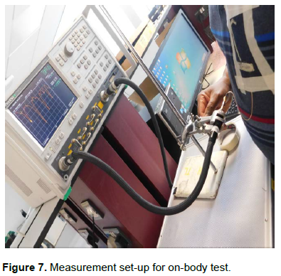
Fabric antenna measurements were performed when worn on- and off-body (Figure 7). The effect of the human body on input match characteristic of fabric antenna was measured by placing the antenna on the chest. Measurements were performed to study S11 response when the wearable antennas were placed on the front or chest region of the body.
Comparing the results of the detuning effect when the antenna is in free space and 0 mm, there is a shift in frequency to the right because the embroidered antennas were shielded from the body. The detuning effect can be minimized by using EBG materials (Ferreira et al., 2017).
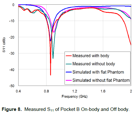
Simulated and measured reflection coefficients (S11) for the pocket antenna both with and without the presence of flat body Phantom are shown in Figure 8. The measurements for without the body S11 was 900 MHz at -32.31 dB, a bandwidth (841-965 MHz) of 13.78%. The measured with body resonant frequency was 858 MHz at -43.4 dB and bandwidth (805-936 MHz) of 15.26%. The measurements for simulation without flat Phantom was 907 MHz at -16.94 and -10 bandwidth (858-956 MHz) while for simulation with flat Phantom was 868 MHz at -22.52dB and -10 dB bandwidth (805-907 MHz).
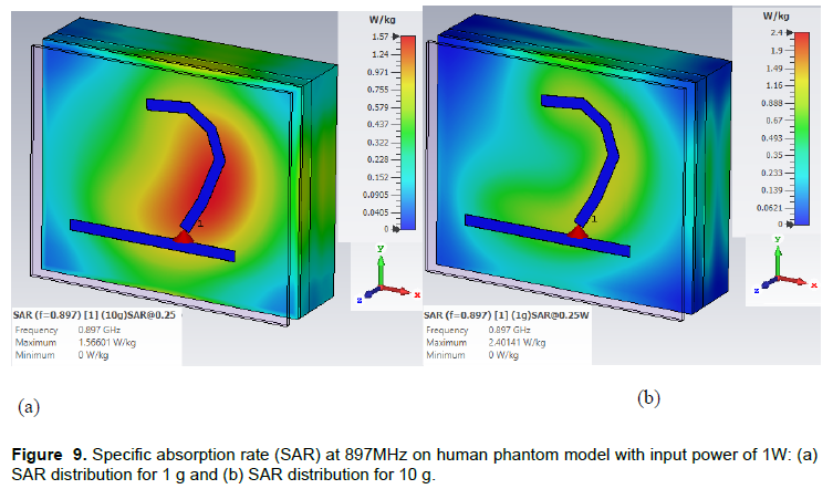
The designed antennas are to operate in proximity to the human body, when they are placed on layers of a garment. The antenna was simulated in CST Microwave Studio using flat body Phantom (Figure 9) considering separation distances from the human body. The antenna was simulated in free space. For this, pocket antenna simulation and average clothing thickness of ![]() was considered. The air gap between the felt fabric substrate and the human body was 3 mm. The properties and parameters of the flat body Phantom are: Muscle (εr = 52.79; σ = 1.705,thickness = 23mm) skin ?εr = 31.29; σ = 5.0138, thickness = 2mm) and fat (εr = 5.28; σ = 0.1, thickness = 8mm) (Ali et al., 2017).
was considered. The air gap between the felt fabric substrate and the human body was 3 mm. The properties and parameters of the flat body Phantom are: Muscle (εr = 52.79; σ = 1.705,thickness = 23mm) skin ?εr = 31.29; σ = 5.0138, thickness = 2mm) and fat (εr = 5.28; σ = 0.1, thickness = 8mm) (Ali et al., 2017).
Pocket B antenna simulation was performed on the human phantom using CST Microwave Studio. The CST uses the IEEE C95.3 standard averaging method. The referenced input power of 0.25 W produced a SAR distribution (Figure 9). The simulated results are 2.401 W/kg for 1 g of tissue and 1.57 W/kg for 10 g of tissue. The lossy nature of human tissues causes energy to be absorbed when electromagnetic waves are propagating. At lower input power, the SAR limit is within the acceptable limit (ICNIRP 1998).
For the chest measurements; the antenna was mounted directly on a shirt of about 3 mm thickness (measured). The antenna was placed near the body which may account for slightly significant detuning effects because of the lossy nature of the human body. When the antenna was worn on the body from the S11 response plot, compared to the results of the detuning effect when the antenna was Off-body and On-body, a shift in frequency to the left was observed. This shows that the pocket antenna is suitable and efficient over 120 MHz band from 805 to 936 MHz. Over this band, the pocket antenna produced a gain of 1.9 and 7.85 dB without and with flat body Phantom, respectively. The human body lowers the resonance frequency of the wearer at 900 MHz
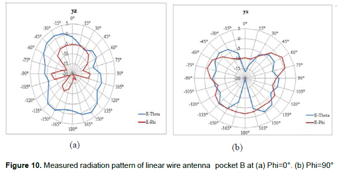
The elevation and Azimuth cuts were measured for the antenna radiation patterns in the anechoic chamber. Four patterns at 900 MHz were measured in the chamber except for one pattern (Figure 10). The antenna under test (AUT) was mounted on the positioner in a horizontal plane in an anechoic chamber. The AUT axis was aligned with the axis of rotation for easy tracking from the transmitter. A stable pattern was observed but not completely omni-directional giving the antenna a good coverage. The pattern indicates back and minor lobes that may occur due to the effects of linear perfectly conducting ground plane. The linear ground is resonating and radiating.
CONCLUSION
In this paper, real valued GA was applied to design linear wire antennas by considering return loss. The simulation results are in good agreement with measurements. Wire structure, comprising seven segments and five angles were considered. A novel method was introduced to design a linear wire antenna. By using genetic algorithms with NEC2 to simulate and measure antennas that cover GSM 900 (850-950 MHz), the results showed that all the four optimized antennas had good efficiency that made them suitable for communication applications. This procedure of using GA with NEC2 to optimize antenna efficiency yields good designs, showing remarkable performance in terms of bandwidth and return loss (S11). There were good agreements between simulated S11 results with measured optimized linear wire antennas. The compactness of the embroidered antenna size (reduced length by 55% of quarter wavelength) makes the antenna height small for wearable surfaces. The proposed antenna designs were well matched as the bandwidth covers GSM 900MHz.
CONFLICT OF INTERESTS
The authors have not declared any conflict of interests.
REFERENCES
|
Ali U, Ullah S, Khan J, Shafi M, Kamal B, Basir A, Flint JA, Seager RD (2017). Design and SAR analysis of wearable antenna on various parts of human body, using conventional and artificial ground planes. Journal of Electrical Engineering and Technology, 12(1), 317-328. |
|
|
Altshuler EE, Linden DS (1997). Wire-antenna designs using genetic algorithms, IEEE Antennas Propagation Magazine 39(2):33-43. |
|
|
Balanis CA (2016). Antenna theory: analysis and design. John Wiley and Sons. |
|
|
Choi K, Jang DH, Kang SI, Lee JH, Chung TK, Kim HS (2015). Hybrid algorithm combing genetic algorithm with evolution strategy for antenna design. IEEE transactions on Magnetics, 52(3):1-4. |
|
|
Choo H, Rogers R, Ling H (2002). Design of electrically small wire antennas using genetic algorithm taking into consideration of bandwidth and efficiency. In IEEE Antennas and Propagation Society International Symposium (IEEE Cat. No. 02CH37313) (Vol. 1: pp. 330-333). |
|
|
Deep K, Thakur M (2007). A new crossover operator for real coded genetic algorithms. Applied mathematics and computation 188(1):895-911 |
|
|
Ferreira D, Pires P, Rodrigues R, Caldeirinha RF (2017). Wearable Textile Antennas: Examining the effect of bending on their per-formance. IEEE Antennas and Propagation Magazine 59(3):54-59. |
|
|
Ghatak R, Poddar DR., Mishra RK (2009), Design of sierpinski gasket fractal microstrip antenna using real coded genetic algorithm. IET Microwave. Antennas Propag. 3(7):1133-1140. |
|
|
Hornby G, Globus A, Linden D, Lohn J (2006). Automated antenna design with evolutionary algorithms. In Space 2006 (p. 7242). |
|
|
Guideline ICNIRP (1998). Guidelines for limiting exposure to time-varying electric, magnetic, and electromagnetic fields (up to 300 GHz). Health phys, 74(4):494-522 |
|
|
Jagodzinska K, Wysota M, Walkowiak M (2008). Electrically small linear antennas generated with a genetic algorithm. In 2008 1st International Conference on Information Technology (pp. 1-4). IEEE. |
|
|
Johnson JM, Rahmat-Samii V (1997). Genetic algorithms in engineering electromagnetics. IEEE Antennas and Propagation Magazine 39(4):7-21. |
|
|
Mehrparvar M, Izadi OH, Oraizi H (2012). Design of microstrip spiral antenna using Genetic Algorithm. In Telecommunications (IST), Sixth International Symposium pp. 11-14. |
|
|
Seager R, Zhang S, Chauraya A, Whittow W, Vardaxoglou Y, Acti, T, Dias T (2013). Effect of the fabrication parameters on the performance of embroidered antennas IET Microwave Antennas Propagation 7(14):1174-1181. |
|
|
Yang HC, Azeez HI, Wu CK, Chen WS (2017). March. Design of a fully textile dual band patch antenna using denim fabric. In 2017 IEEE International Conference on Computational Electromagnetics (ICCEM):185-187. |
|
|
Zhang S, Chauraya A, Whittow W, Seager R, Acti T, Dias T, Vardaxoglou Y (2012, November). Embroidered wearable antennas using conductive threads with different stitch spacings. In 2012 Loughborough Antennas and Propagation Conference (LAPC) (pp. 1-4). IEEE. |
|
Copyright © 2024 Author(s) retain the copyright of this article.
This article is published under the terms of the Creative Commons Attribution License 4.0


